

Autani SMT-131 Wireless Digital Thermostat

Description
The Autani SMT-131 Digital Thermostat is perfect for all applications requiring a simple to use thermostat where energy savings is paramount. The SMT-131 is a wirelessly networked, thermostat for use with Autani’s EnergyCenter HVAC Management System EnergyCenter manages heating and cooling based upon schedule, occupancy, and demand response events.
Integrated PIR and door or window inputs are provided to automatically alter the thermostat’s control set point and mode to eliminate energy waste if the room is found unoccupied or if doors and windows are left open. Analogue control outputs and relay outputs are also provided to control the latest variable capacity systems as well as modulating valves as needed. This includes support for DC fan motors with minimum and maximum fan speed limit control. Optional corridor displavs can be connected should the SMT-131 be used in the hotel industry. The HOT-243 corridor display will show room status
and the guest’s need for housekeeping at the touch of a button on the SMT-131 touch screen. Integrated Modus RTU permits the SMT-131 to be remotely accessed by a building BMS or EnergyCenter for true remote control and accessibility.
Applications
SMT-131 Thermostats are suitable for renovation, upgrade, and new construction projects.
- Private & Open Offices
- Corridors & Hallwavs
- Classrooms & Gymnasiums
- Warehouse Spaces & Manufacturing Areas
- Patient Care Rooms
- Transportation Terminals
- Retail & Grocery Stores
Features
- Bright Backlit Touch Screen
- Intuitive Operation
- Relay & 0-10V Equipment Control Outputs
- Single or Three Fan Speed Control
- Heat Pump or Heat Cool Control Logic
- 0-10V DC Fan Control
- Extensive Installer Options Menu
- PIR, Window and Door Status Inputs
- Inbuilt Logic for Room Occupancy
- Integrated Modbus RTU Communications
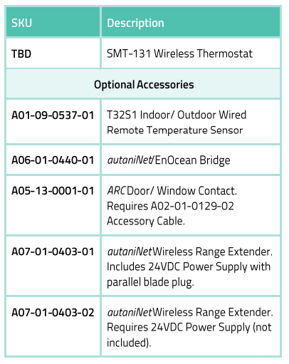
- Optional Remote Sensors) Available
- Switched Occupancy Input
- Optional Door Station Input (shown)
- CE & Ctick Certified
- Easily integrates with Autani’s EnergyCenter platform to create a building- or campus-wide network of smart, energy-saving devices autaniNet secure wireless 2.4GHz communications with other network devices
Specifications
ELECTRICAL
- Power: 24V +/- 20% 50/60 Hz
- Relay Voltage: 24VAC @ 1 Amp Max
OUTPUTS
- Relay Outputs: Fan Low/Med/Hi/Heat/Cool
- Analogue Outputs: Heat / Cool Fan
- 0-10 Outputs: 5ma Max
PHYSICAL
- Touch Method: “XY” Resistive
- Back Light: White LED
- Back Light Life: 40,000 Hours to Half Intensity
- Size: 103mm X 113mm X 26mm
ENVIRONMENTAL
- Operating Temperature: -5°C to 50°C (23F to 122F)
- Operating Rh: 0 To 95% (Non Condensing)
ACCURACY
- Sensor Accuracy: +/- 0.5°C at 25°C (1F at 77F) (Calibratable)
- Timer Accuracy: +/- 2.5 Minimum Per Year
OTHER SPECS
- Warranty: 3 Years
- Approvals: CE & Ctick
- Communications: Modus RTU 9.6k
RADIO NETWORK (autaniNet)
- IEEE 802.15.4-2003 2.4GHz ISM
- Range: Up to 2000′ LOS transmit/ receive
Modbus Objects
- Equipment Status: 5 Relay Coils & all 0-10V Output
- Room Temperature: 0.1°C Resolution
- Guest Set Point: 0.5 °C Resolution
- Thermostat Status: On / Off / Mode
- Auto Set Temperature Reset: On/Off, Value Adjustment
- Fan Speed: Off / 1 / 2 / 3 / Auto + 0-10V
- Fan Mode: Auto / Manual / Ventilation
- Fan Purge Period: 0-10 Minutes
- Unoccupied Heat & Cool Set: 0.5°C (1F) Resolution
- Unoccupied Fan Mode: Off / 1 / 2 / 3 / Auto
- Room Occupancy Status: Empty / Occupied
- All Digital Input Status: PIR/Door/Window DI & SI
- Occupancy Input Delays: For PIR/Door & Window Inputs
- Door Station Status: Make Up Room / Do Not Disturb
- Native Temperature Displav: C / F
- Switch Settings: Binary of all Switches
- Heating / Cooling Called: 0.1 °C Resolution
- O-10V Heat & Cool Output: Output Voltage 0. 1V Resolution
- Min & Max 0-10V Limits: For Fan Analogue Output
- High Temperature Limit: 5°C to 35°C (41F to 95F)
- Low Temperature Limit: 6°C to 36°C (43F to 97F)
- Equipment Hvsteresis: 0.5°C to 1.5°C (1F to 2.7F)
- Auto Off Period: Off to 10 Hours
- Unit Run Time Log: 1/10 Hours Resolution
- Back Light Options: Off / On / High /Low / Auto
- Modbus Baud: 9.6k
Terminal Wiring
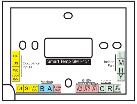
YELLOW: ANCILLARY INPUTS
- PIR: PIR Movement Detector
- DS: Door Switch
- WC: Window Contact
- DI: Digital Input (Selectable Functions)
- SI: Sensor input (Selectable Functions)
- Com 0-V: Common Reference
BLUE: MODBUS
- B: Data B
- A: Data A
PINK: 0-10V OUTPUTS
- A3 Fan: Digital Fan Control
- A2 Heat: Heat Valve Control
- A1 Cool: Cool Valve Control
- Com 0-V: Common Reference
GREEN: EQUIPMENT RELAYS
- L: Low Fan Speed
- M: Medium Fan Speed
- H: High Fan Speed
- Y: Cool (or Compressor)
- W O/B: Heat (or Reversing Valve)
- R: Control Active 24+
- C: Control Common 24-
Ordering Information
www.autani.com
443.320.2233
REFERENCE
DOWNLOAD MANUAL:
Autani SMT-131 Wireless Digital Thermostat Product Specification GUIDE
OTHER MANUALS:
Autani SMT-131 Wireless Digital Thermostat Quick Installation Sheet
Autani SMT-131 Wireless Digital Thermostat Product Specification GUIDE
Leave a Reply