
Aube Technologies TH146-P-2H1C Programmable Thermostat

Introduction
Applications
The TH146-P-2H1C programmable controller can be used with any of the following heating/cooling systems:
- Heat pump – 1H1C, 2H1C
- HVAC – 1H, 1C, 1H1C
The following devices can be connected to the controller:
- air recirculation fan
- humidifier
- dual-register meter (dual energy)
- remote control device (for the unoccupied mode)
Supplied Parts
- CT280-2H1C control module
- TH146-P console with two wall anchors and mounting screws
- AC144-03 outdoor temperature sensor (3 m or 10 ft) with mount-ing clip (see section 2.6)
Accessories
- RC845 relay (see section 2.4)
- AC146-410 plenum temperature sensor (see section 2.7)
- CT241 telephone controller (see section 2.9)
- AC130-12 wall plate
Installation
Control Module (CT280-2H1C)
Configure the control module according to your type of heating/cool-ing system using DIP switches on the back of the module.

Install the control module near the heating/cooling system, away from any heat source.
User Console (TH146-P)
Install the console in a central location. Avoid locations with air drafts (e.g., top of staircase or air outlet) or stagnant air (behind a door). Do not install the console on a wall hiding air ducts nor expose it to direct sunlight.
NOTE: If this controller replaces an old thermostat, any two of the wires that were connected to the thermostat can be used to connect the user console to the control module. The maximum wiring length is 30 m (100 ft).
- Choose a location about 1.5 m (5 ft) above the floor on an inside wall.
- Loosen the captive screw under the console.
- Detach the console from its base by pulling the bottom section. Secure the base using the wall anchors and screws.
- Connect the console to controller terminals TH and TH (no polarity).
Heating/Cooling System
The terminals used to connect the heating/cooling system depend on the type of system. See the appropriate wiring table on page 4.
RC845 Relay
If you have an add-on installation, you might need an RC845 relay to connect the furnace (auxiliary heating) and its fan to the control-ler. Install the relay near the control module and connect the wires as follows:
- relay terminals W, G and C to controller terminals W, G and C.
- relay terminals T and T to the appropriate furnace terminals: T and T (oil); TH and TH (gas); R and W (electric).
NOTE: Refer to the relay’s installation instructions for more details.
Humidifier
Connect the humidifier in series with the power supply between controller terminals H and H (dry contact).
Outdoor Sensor (AC144-03)
The outdoor sensor is required for the following:
- outdoor temperature display
- balance points (heat pumps only, see section 4.2)
- defrost point (heat pumps only, see section 4.3)
- automatic humidity control (see section 7.2)
When installing the sensor, observe the following guidelines:
- Avoid locations where the sensor can be covered with snow or exposed to direct sunlight.
- Avoid air outlets and concealed chimneys or stove pipes.
Install the sensor using its mounting clip and connect it to controller terminals OS and CS (no polarity).
NOTE: The maximum wiring length is 30 m (100 ft).
Plenum Sensor (AC146-410)
The plenum sensor is required for the following:
- low temperature limit inside the plenum (HVAC only)
- high temperature limit inside the plenum (HVAC only)
- fan limit if gas heating is used (HVAC only)
- high pressure protection during defrost cycle (This protection is generally needed for add-on installations only. It is not needed if the heat pump is not connected to the controller terminal WW.)
Install the sensor on the side of the plenum and position it such that its aperture faces the air flow.
Connect the sensor to controller terminals PS and CS (no polarity). For more information, refer to the instructions provided with the sen-sor.
NOTE: The maximum wiring length is 30 m (100 ft).
Dual-energy Input
NOTE: The dual-energy input can be used only with a heat pump equipped with auxiliary heat.
The dual-energy input can be connected to the dual-register meter equipped with a normally open (NO) dry contact. Connect the controller terminals DE and CC to the meter terminals (yellow and red wires).
The contact closes when the outdoor temperature drops below the temperature setting on the meter. When the contact is closed, the heat pump is disabled and only the auxiliary heat can be used.
Unoccupied Mode Input
To use the unoccupied mode, the controller requires a remote control device such as Aube’s CT241 telephone controller equipped with a normally open (NO) dry contact placed between terminals UN and CC of the controller. The unoccupied mode is activated when the contact closes. (See section 6.4.)
Configuration
Configuration Switches
To access the configuration switches, loosen the captive screw under the console and separate the console from its base by pulling the bottom section.
Access Mode (SW1-1)
- INST: Installer mode. Gives access to all configuration parameters.
- NOTE: In installer mode, the short-cycle protection is disabled and the interstage delay is reduced to 1 minute.
- USER: User mode. Gives access to configuration parameters 1 to 4 only.
Keypad Lock (SW1-2)
- I: The keypad is locked. Settings cannot be changed.
- O: The keypad is unlocked.
Software Configuration
- Place the console in Installer mode (INST) using the SW1-1 switch on the back of the console.
- Press the Mode button for 3 seconds to access the configuration menu (see page 8). The first menu item (parameter) is displayed.
- To view another menu item, briefly press the Mode button.
- To modify a parameter, press either
 button.
 - To exit the configuration menu, press
 .
. - Return the console to User mode (USER).
Principles of Operation
Automatic Heating/Cooling Changeover
With automatic heating/cooling mode changeover, there’s no need to adjust the controller at every change of season or weather condition. The controller switches automatically between heating mode and cooling mode to maintain the desired temperature.
Manual Mode
When the controller is in manual mode, the heating/cooling mode changeover occurs as follows:
- The controller switches to cooling mode when the indoor temperature is higher than the setpoint by more than 1.5°C (2.5°F) for 15 minutes.
- The controller switches the heating mode when the indoor temperature is lower than the setpoint by more than 1.5°C (2.5°F) for 15 minutes.
Automatic Mode
When the controller is in automatic mode, it follows the programmed schedule. Two temperature settings (heating setpoint and cooling setpoint) are programmed for each period of the schedule. The heating/cooling mode changeover occurs as follows:
- When the controller is in heating mode, the indoor temperature is maintained at the heating setpoint. However, if the temperature rises and remains above the cooling setpoint for 15 minutes, the controller will switch to cooling mode.
- When the controller is in cooling mode, the indoor temperature is maintained at the cooling setpoint. However, if the temperature drops and remains below the heating setpoint for 15 minutes, the controller will switch to heating mode.
Balance Points (heat pumps only)
Balance Points are used to disable the heat pump or the auxiliary heating when the outdoor temperature is below or above a set temperature.
- When the outdoor temperature is below the Balance Point Low (bP L), the heat pump is disabled and only auxiliary heating can be used (see page 8, item 5).
- When the outdoor temperature is above the Balance Point High (bP H), the auxiliary heat is disabled and only the heat pump can be used (see page 8, item 6).
NOTE: Balance Points cannot be used if the AC144-03 outdoor temperature sensor is not connected to the controller.
Heating During Defrost (heat pumps only)
The auxiliary heat is activated during defrost except under the following conditions:
- When the outdoor temperature is above the defrost point (see page 8, item 7). Note: This condition will not apply if the AC144-03 outdoor sensor is not connected to the controller.
- When the plenum temperature is above 40°C (104°F). The auxiliary heat is re-activated when the plenum temperature drops below 32°C (90°F). Note: This condition will not apply if the AC146-410 plenum sensor is not connected to the controller.
NOTE: The auxiliary heat’s short-cycle protection is disabled during defrost.
Types of Heat Pump Installations
The controller can be configured for either of the following types of heat pump installations (see page 8, item 8).
- Add-on Installation: This type of installation is performed when adding a heat pump to an existing furnace. When the heat pump is installed, the furnace becomes the auxiliary heat source. In this type of installation, the indoor coils are usually installed downstream of the auxiliary heat source. When the controller is configured for an add-on installation, the heat pump is disabled during auxiliary heating to prevent overpressure.
- New Installation: In this type of installation, as there is not already a furnace, the auxiliary heat source is installed at the same time as the heat pump. In this type of installation, the indoor coils are located upstream of the auxiliary heat. When the controller is configured for a new installation, the heat pump and the auxiliary heat can operate simultaneously.
Interstage Delay
Interstage Delay is the time allocated for the temperature to return to an acceptable value when it deviates too far from the setpoint. If this time has elapsed, the next heating or cooling stage is activated. The heating or cooling stage will be deactivated when the temperature returns to an acceptable value. The Interstage Delay is fixed at 4 minutes if the controller is configured for an HVAC system and is user-adjustable if it is configured for a heat pump (see page 8, item 9).
Low and High Temperature Limits
Low Temperature Limit (LLMT) and High Temperature Limit (HLMT) are used to keep the plenum from becoming too cold or too hot. During cooling, if the plenum temperature is lower than LLMT, a cooling stage is deactivated starting with the one that was last activated. If, after a while, the temperature is still too low, another cooling stage is deactivated and so on. Likewise, during heating, if the plenum temperature is higher than HLMT, a heating stage is deactivated starting with the one that was last activated. If, after a while, the temperature is still too high, another heating stage is deactivated and so on. (see page 8, items 10 and 11.)
WARNING: LLMT and HLMT can be used in parallel with an UL353-approved device but they do not replace such device.
NOTE: LLMT and HLMT cannot be used if the plenum temperature sensor is not connected to the controller.
Smart Fan
When Smart Fan is enabled (see page 8, item 15), the fan operates as follows:
- During periods 2 and 4 of automatic mode and during the unoc-cupied mode (i.e., when you are away from home or sleeping), the fan operates only when heating or cooling is activated.
- The fan operates continuously the rest of the time.
NOTE: For Smart Fan to work, set the fan to On (see section 5.3).
Wiring Tables
| Heat Pump | |||
| Terminal | Device | 1H1C | 2H1C |
| TH |
Console |
Connect the console between the TH terminals (no polarity) |
|
| TH | |||
| PS | Plenum sensor | Connect the plenum sensor between the PS and CS terminals (no polarity) | |
| CS | Common S | Common terminal for the plenum sensor and the outdoor sensor | |
| OS | Outdoor sensor | Connect the outdoor sensor between the CS and OS terminals (no polarity) | |
| DE | Dual Energy | Connect the dual-register meter between the DE and CC terminals (no polarity) | |
| CC | Common C | Common terminal for the dual-energy meter and the unoccupied mode input | |
| UN | Unoccupied mode input | Connect a dry contact between the UN and CC terminals (no polarity) | |
| H |
Humidifier (24 Vac / 1 A) |
Connect the humidifier between the H terminals (dry contact) |
|
| H | |||
| R |
Power (24 Vac) |
Ö | Ö |
| C | Ö | Ö | |
| Y | Compressor (24 Vac / 1 A) | Ö | Ö |
| W | Auxiliary heat (24 Vac / 1 A) | Ö | |
| O/B | Reversing valve (24 Vac / 1 A) | Ö | Ö |
| G | Fan (24 Vac / 1A) | Ö | Ö |
| L | Fault (24 Vac / 5 mA) | Ö | Ö |
| WW | Defrost (24 Vac / 5 mA) | Ö | Ö |
| HVAC | ||||
| Terminal | Device | 1H | 1C | 1H1C |
| TH |
Console |
Connect the console sensor between the TH terminals (no polarity) |
||
| TH | ||||
| PS | Plenum sensor | Connect the plenum sensor between the PS and CS terminals (no polarity) | ||
| CS | Common S | Common terminal for both plenum sensor and outdoor sensor | ||
| OS | Outdoor sensor | Connect the outdoor sensor between the OS and CS terminals (no polarity) | ||
| DE | Not used | |||
| CC | Common C | Common terminal for the unoccupied mode input | ||
| UN | Unoccupied mode input | Connect a dry contact between UN and R terminals (no polarity) | ||
| H |
Humidifier (24 Vac / 1 A) |
Connect the humidifier between the H terminals (dry contact) |
||
| H | ||||
| R |
Power (24 Vac) |
Ö | Ö | Ö |
| C | Ö | Ö | Ö | |
| Y | Cooling unit (24 Vac / 1 A) | Ö | Ö | |
| W | Heating unit (24 Vac / 1 A) | Ö | Ö | |
| O/B | Not used | |||
| G | Fan (24 Vac / 1 A) | Ö | Ö | Ö |
| L | Not used | |||
| WW | Not used | |||
Wiring Diagram: 2H1C Heat Pump
New Installation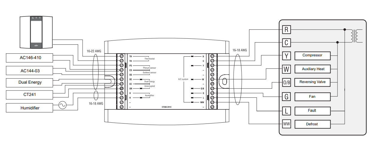
Wiring Diagram: 2H1C Heat Pump
Add-on Installation
Wiring Diagram: 1H1C HVAC
| Item | HP | HVAC | Parameters | Display | Options | Default | Description |
| 1 | Ö | Ö | Time format | Hr | 12 Hr / 24
Hr |
24 Hr | Select the time display format. |
|
2 |
Ö |
Ö |
Early Start |
E5
|
On / OF |
OF |
• On: Heating or cooling starts in advance (as determined by the controller) so that the desired temperature is attained at the set times.
• OF (Off): Heating or cooling starts at the set times. NOTE: Early Start applies for periods 1 and 3 (P1 and P3) only. When this feature is enabled, heating or cooling will start in advance of the set time for P1 and P3 but will start at the set time for P2 and P4. |
|
3 |
Ö |
Ö |
Automatic daylight savings adjustment |
dL5
|
OF / 1 / 2 |
OF |
• OF (Off): The function is deactivated.
• 1 : The controller switches to daylight savings time on the first Sunday of April and to normal time on the last Sunday of October. • 2 : The controller switches to daylight savings time on the second Sunday of March and to normal time on the first Sunday of November. |
| 4 | Ö | Ö | Temperature format |
|
°C / °F | °C | Select the temperature display format. |
|
5 |
Ö |
Balance point low |
|
-30 to 10°C
(-22 to 50°F) |
-10°C (14°F) | Set the bP L limit (see section 4.2).
NOTE: Lower bP L below its minimum (- -) if you do not wish to use this function. |
|
|
6 |
Ö |
Balance point high |
|
-5 to 30°C
(23 to 86°F) |
5°C (41°F) | Set the bP H limit (see section 4.2).
NOTE: Raise bP H above its maximum (- -) if you do not wish to use this function. |
|
|
7 |
Ö |
Defrost point |
|
-10 to 15°C
(14 to 59°F) |
10°C (50°F) | Set the defrost point temperature (see section 4.3).
NOTE: Raise the defrost point above its maximum (- -) if you do not wish to use this function. |
|
|
8 |
Ö |
Installation type |
|
Ad / nr |
Ad |
Set according to the type of heat pump installation (see section 4.4).
• Ad (add-on): Use this setting when the indoor coils are located down- stream of the auxiliary heat source. This is generally the case for add- on installations. • nr (normal): Select this setting when the indoor coils are located upstream of the auxiliary heat source. This is generally the case for new installations. |
|
| 9 | Ö | Auxiliary interstage delay | HIST
|
5 to 90 min. | 30 min. | Set the interstage delay for the auxiliary stage (see section 4.5). | |
|
10 |
Ö |
Low temperature limit | |
-10 to 20°C
(14 to 68°F) |
5°C (41°F) | Set the low temperature limit of the plenum (see section 4.6).
NOTE: This function is not used if you lower LLMT below its minimum (- -) or if the plenum sensor is not connected to the controller. |
|
|
11 |
Ö |
High temperature limit | |
30 to 90°C
(86 to 194°F) |
70°C (158°F) | Set the high temperature limit of the plenum (see section 4.6).
NOTE: This function is not used if you raise HLMT above its maximum (- -) or if the plenum temperature sensor is not connected to the controller. |
|
|
12 |
Ö |
Ö |
Cycles per hour |
 |
2 to 6 |
4 |
Select the number of heating/cooling cycles per hour. For optimal heating control, use the setting that matches your system as follows: 3=20 min (hot water, 90%+ high-efficiency furnace), 4=15 min (gas or oil), 5=12 min
(gas or oil), 6=10 min (electric). |
|
13 |
Ö |
Heat type |
|
GA / EL |
EL |
This setting determines the fan operation in automatic mode when the system is in heating mode.
• EL (electric heating): The fan starts and stops at the same time as heating. • GA (gas or oil heating): The fan starts when the temperature inside the plenum rises above the Fan Limit (see item 14) and stops when the temperature drops 12°C below the Fan Limit. Note: The fan will not start if the plenum temperature sensor is not connected to the con- troller. |
|
|
14 |
Ö |
Fan limit |
|
38 to 90°C
(100 to 194°F) |
80°C (176°F) |
This parameter is available only when gas heating is selected (see item 13). WARNING: FLMT can be used in parallel with an UL353-approved device but they do not replace such device.
NOTE: The fan will not start if you raise FLMT above its maximum (–). |
|
| 15 | Ö | Ö | Smart Fan | |
On / OF | OF | On: Smart Fan is On (see section 4.7). OF: Smart Fan is Off. |
| 16 | Ö | Ö | Temperature setback | |
0 to 9°C
(0 to 16°F) |
0°C (0°F) | Set the amount of temperature setback when the controller is placed in Unoccupied mode (see section 6.4). |
|
17 |
Ö |
Ö |
Humidifier operating mode |
|
Co / HE / Fn |
Fn |
• Co (conventional): The humidifier will operate if the humidity is too low. If the fan is not already On, it will turn On at the same time as the humidifier.
• HE (heat): The humidifier can operate only when heating is activated. • Fn (fan): The humidifier can operate as long as the fan is running, whether the heating is activated or not. NOTE: The humidifier is disabled when cooling is activated. |
| Note: Only items 1 to 4 are available when the controller is placed in user mode (SW1-1 switch). | |||||||
Reference
Download manual:
Aube Technologies TH146-P-2H1C Programmable Thermostat Installation Guide
OTHER MANUALS:
Aube Technologies TH146-P-2H1C Programmable Thermostat User Guide
![]()
Aube Technologies TH146-P-2H1C Programmable Thermostat Installation Guide
Leave a Reply