
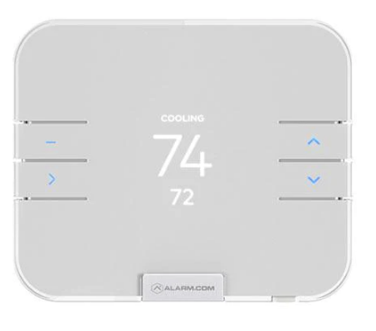
Alarm.com ADC-T3000 Smart Thermostat
Installation precautions
- Before installing or servicing the thermostat, turn off the power to the system at the circuit breaker.
- Leave the power off until you have finished installing or servicing.
- Shorting the electric terminals at the control on the heating or cooling system may damage the thermostat. Do not test the system this way.
- You must follow all local codes and ordinances for wiring the system.
- This thermostat should only be powered by two AAA alkaline batteries or a listed Class 2 power supply at 24 VAC (C-Wire or wall transformer).
- An amperage higher than 1 amp through each thermostat terminal may cause damage to the thermostat.
- Verify that the system is 24 VAC. If the old system is labeled as 120 or 240 volts or has wire nuts, the system is high voltage.
- Do not install the thermostat to a high-voltage system. Contact a local HVAC professional for help.
Questions?
Visit: www.alarm.com/supportcenter or contact your service provider.
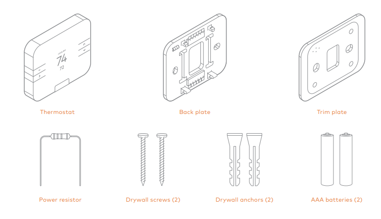
In the box
Recommended tools

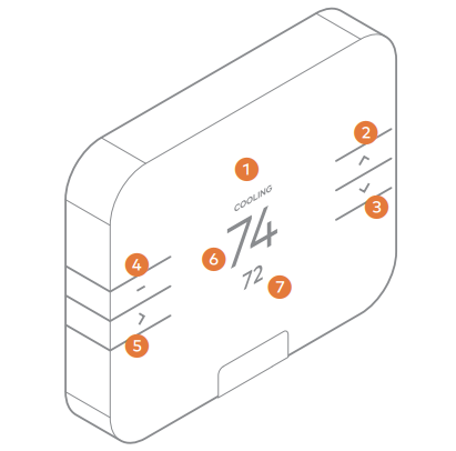
Thermostat overview
Buttons
- MENU: Access options to change the mode, fan, settings, and other features.
- UP: Adjust setpoint up or navigate the MENU.
- DOWN: Adjust the setpoint down or navigate the MENU.
- SELECT: Select options in the MENU.
Modes
- HEAT: Will activate the heating system.
- COOL: Will activate the air conditioner.
- AUTO: Will select either the HEAT or COOL mode automatically.
- EMER: For use with heat pumps only. Will bypass the heat pump and enable auxiliary/emergency heat.
- OFF: The system will not heat or cool.
Display
 HEATING: Illuminated in HEAT, EMER, or AUTO mode when the thermostat is calling for heat.
COOLING: Illuminated in COOL or AUTO mode when the thermostat is calling for cool.Illuminated when the thermostat is using one or more Alarm.com Temperature Sensors.
- Display
- Up
- Down
- Menu
- Select
- Room Temperature
- Setpoint
Location
If replacing an old thermostat, the new thermostat can be mounted in its place. If a new location is desired it will be necessary to move the wiring. New installation and relocation should follow the accompanying guidelines to ensure the most accurate temperature reading and ease of use.
- Mount thermostat on an inside wall, approximately 5 ft. (1.5m) above the floor in a frequently used room.
- Do not install in locations near appliances or devices that affect the local temperature such as televisions, lamps, or dryers.
- Avoid areas that are exposed to large temperature variances, such as direct sunlight, near an AC unit, above or below auxiliary heat and air vents, and drafts from windows.
- Be aware of what is on the other side of the wall where the thermostat is being installed. Do not install on walls adjacent to unheated rooms, stoves, or housing hot water pipes.
- Damp areas will not only affect the humidity reading of the thermostat but could lead to corrosion and shorten the life of the thermostat.
- Install in a location with good air circulation. Stagnant air will not accurately reflect the rate of temperature change in the room.
- Avoid areas behind open doors, corners, and alcoves.
- Wait until construction and painting are finished before installation.
Preparation
Test the system
Verify that the heating and/or cooling system is operating properly before you try to install the new thermostat.
CAUTION: Do not test the system by shorting electric terminals at the furnace or air conditioner. This may damage the thermostat.
Turn the power off
Turn all heating and cooling systems off. This can be done at the circuit breaker.
CAUTION: Do not remove the existing thermostat until power has been turned off at the circuit breaker. Once the power to the heating and cooling systems is off, perform the following steps:
Remove the thermostat cover
Remove the cover from the existing thermostat. Do not disconnect the wires yet.
Make sure the wires are identified correctly. If you have an unidentified wire, it may be necessary to identify the wire where it connects to the heating or air conditioning equipment.
CAUTION: Wiring can vary for each manufacturer. Identify all wiring before removing it from the existing thermostat. Take a picture of the wires before you detach them from the existing thermostat for future reference. Disconnect all of the wires and remove the existing thermostat. Remember to secure the wires so they don’t fall into the wall. 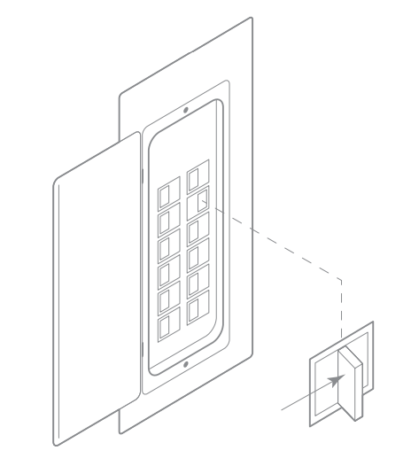
Prepare the wires
Follow these guidelines for safe and secure wire connections:
- Ensure the wires are a proper gauge between 18-24 AWG.
- Make sure wires have exposed straight ends about 1/4” long.
CAUTION: Verify that the system is 24 VAC. If the old system is labeled as 120 or 240 volts or has wire nuts, the system is high voltage. Do not install the thermostat to a high-voltage system. Contact a local HVAC professional for help.
Install the back plate
Use the bubble level provided on the back plate as a guide. Mark where the screws will go with a pencil through the screw holes on the back plate. Ensure the top of the back plate is facing up. If necessary, use the trim plate to cover up any marks or holes left by the old thermostat. Attach the trim plate before securing the back plate to the wall. If additional support is necessary, drill holes with a 1/4” drill bit and tap in the drywall anchors.
Installation
Wire your new thermostat
Connect the wires to the new thermostat. If you have extra wires, do not connect the to the new thermostat. Please contact your local HVAC professional for additional assistance.
- If you have R, connect it to RH.
- If you have RH and RC, you do not need a physical jumper to connect the two terminals. RH and RC are connected by a digital jumper.
- Z1 or Z2 can be used for W3, H, DH, or EX.
NOTE: If you have a 2-wire hydronic heating system, you may need to add the power resistor to the system. Connect this resistor to your heating equipment (not the thermostat) between the C and W terminals. Additional information about the power resistor can be found in the Troubleshooting section.
Terminal designations
| Conventional system | |
| Terminal | Description |
| RC | Cooling power |
| RH | Heating power |
|
Z1 |
Configurable W3, H (humidifier control), DH (dehumidifier control),
EX (ventilation) |
|
Z2 |
Configurable W3, H (humidifier control), DH (dehumidifier control),
EX (ventilation) |
| W | Heat stage 1 |
| W2 | Heat stage 2 |
|
C |
Common wire from secondary side of heating transformer (if 2 transformers) |
| Y | Cool stage 1 |
| Y2 | Cool stage 2 |
| G | Fan |
| O | Energized in COOL mode |
| B | Energized in HEAT mode |
| Heat pump | |
| Terminal | Description |
| RC | Cooling power |
| RH | Heating power |
|
Z1 |
Configurable W3, H (humidifier control), DH (dehumidifier control),
EX (ventilation) |
|
Z2 |
Configurable W3, H (humidifier control), DH (dehumidifier control),
EX (ventilation) |
| W | Aux stage 1 |
| W2 | Aux stage 2 |
|
C |
Common wire from secondary side of heating transformer (if 2 transformers) |
| Y | Pump stage 1 |
| Y2 | Pump stage 2 |
| G | Fan |
| O | Energized in COOL mode |
| B | Energized in HEAT mode |
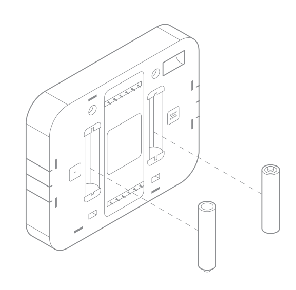
Install the batteries
The thermostat can be powered by a battery or 24 VAC. If a wall transformer is used to power the thermostat, connect between C and RH.
Ensure the batteries are installed following the specified polarity markings on the thermostat.
CAUTION: BATTERY WARNING
- Always replace the batteries as soon as you have low battery levels, indicated by a caution sign and “LOW BATTERY” flashing on the display. If the batteries drain, the thermostat could leave the HVAC system on or off, overheating or freezing the home.
- If the thermostat buttons flash amber when pressed and the screen does not illuminate, the batteries in the thermostat are extremely low. Install fresh batteries immediately.
- Always replace the batteries when they are low to protect the thermostat from damage and corrosion by leaking batteries.
- If the home is unoccupied for a month or more, such as with vacation homes, you should replace the batteries as a preventive measure against battery failure while you are away.
- Always use new batteries as replacements.
Attach the body and back plate
Verify that any excess wire is tucked back into the wall to allow room for the thermostat to sit flush against the back plate. Return the thermostat to the wall plate by pressing the thermostat body firmly into the back plate mounted to the wall. Ensure that the pins on the body are correctly aligned with the back plate. Failure to do so could cause damage to the thermostat.
Turn the power on
Restore power to all the heating and cooling systems. This can be done at the circuit breaker.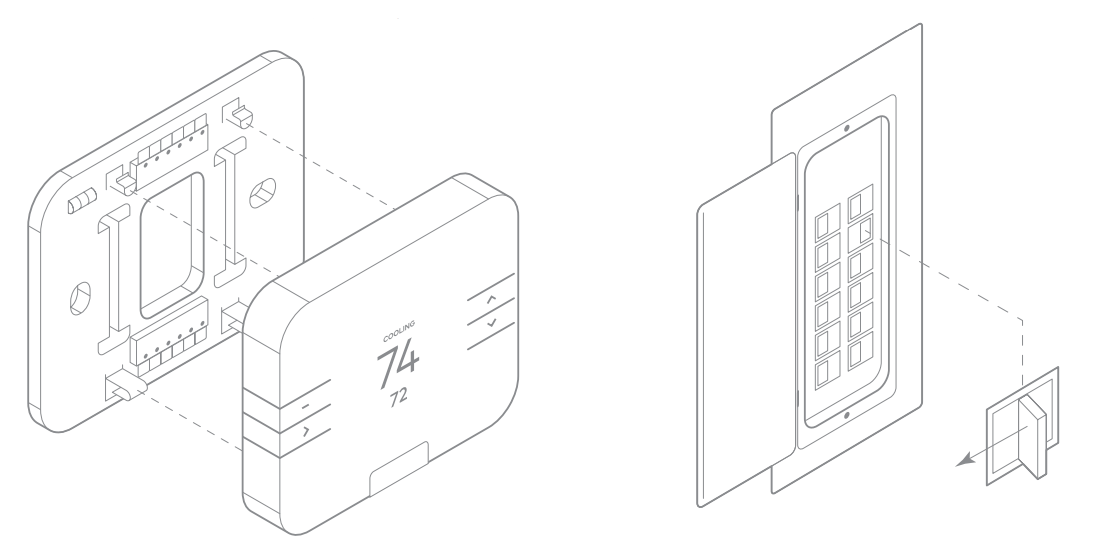
Setup
The thermostat will automatically detect connected wires. Follow the on-screen instructions t complete the thermostat configuration.
NOTE: If the thermostat screen does not show all the connected wires, remove the thermostat from the wall and verify that all wires are properly connected. If issues persist, there may be a problem with automatically detecting your wiring. Please see the Bypassing Wire Detection information in the Troubleshooting section. Depending on the system type and configuration, the thermostat may request the following information during setup:
Heat type
Tells the thermostat whether it should turn on the fan during a heating cycle.
- • Forced air heating: Electric
• Radiant floor heating: Fossil
• Fossil/electric baseboard heating: Fossil
• Radiators: Fossil
• If unsure: Unsure
Backup heat type
Tells the thermostat what type of auxiliary/backup heating the heat pump uses.
- Electric: This is the most common type of backup heating.
- Dual fuel: Some heat pumps use a fossil furnace (for example, natural gas, oil or propane) for backup heating.
- If unsure: The system will automatically detect which heat type is appropriate for your system.
Z1/Z2 terminal function
These are the “dynamic” terminals. If an auxiliary wire has been connected, please specify the function it will perform.
- W3: Third stage of heat or aux
- H: Humidifier
- DH: Dehumidifier
- EX: Ventilation (HRV, VRV, air baffle)
Add to the Z-Wave network
- Put the Z-Wave controller into ADD mode. Refer to the controller documentation for more information.
- Press the MENU button.
- Select SETTINGS.
- Select NETWORK.
- Select ADD.
- Log in to your online account to sync the thermostat with the account, or contact your Service Provider for installation setup.
NOTE: Write your login information below once you have chosen a personal password.
Configure the thermostat
While the default settings online will be sufficient in most cases, you also have the option to change advanced configuration settings, such as Swing, Differential, Fan Circulation Period, Fan Circulation Duty Cycle, Maximum Setpoints, Minimum Setpoints, and Thermostat Lock.
CAUTION: Be careful when changing advanced configuration settings. These configuration settings should only be changed by those familiar with heating and cooling systems’ parameters. Contact a local HVAC professional for help.
Change the default settings
Use the following instructions if you wish to change the default settings on your thermostat.
Changing the temperature display from Fahrenheit to Celsius
- Press the MENU button.
- Select SETTINGS.
- Select USER.
- Select F/C.
- Select C.
Enabling motion-detected wake
This setting will enable the thermostat screen to wake when motion is detected nearby.
- Press the MENU button.
- Select SETTINGS.
- Select USER.
- Select MOTION.
- Select ON.
Note: This feature is only available if the thermostat is AC-powered.
Disabling AUTO mode
- Press the MENU button.
- Select SETTINGS.
- Select USER.
- Select AUTO.
- Select DISABLE.
Humidity control
The thermostat can adjust the humidity level in your home by directly controlling an external humidifier, dehumidifier, or by using the cooling system to dehumidify. For an external humidifier or dehumidifier, the thermostat must be configured to use the Z1 or Z2 terminal. Z1 and Z2 configuration can be found in the Settings section of the Installer menu. If a cooling system is present without an external dehumidifier, the thermostat will extend your cooling cycles in an attempt to reach your dehumidification setpoint.
Changing the humidity mode
Select the mode for which you would like to control humidity.
- Press the MENU button.
- Select SETTINGS.
- Select USER.
- Select HUMIDITY.
- Select MODE. The modes are OFF, DEHUMID, HUMID, and AUTO. AUTO will select either the DEHUMID or HUMID mode automatically.
- Select the desired mode.
Changing the dehumidifier setpoint
Ensure that the humidity mode selected is either DEHUMID or AUTO.
- Press the MENU button.
- Select SETTINGS.
- Select USER.
- Select HUMIDITY.
- Select SETPOINT.
- Select DEHUMID.
- Use the UP/DOWN buttons to adjust to the desired dehumidifier setpoint.
Changing the humidifier setpoint
Ensure that the humidity mode selected is either HUMID or AUTO.
- Press the MENU button.
- Select SETTINGS.
- Select USER.
- Select HUMIDITY.
- Select SETPOINT.
- Select HUMIDly.
- Use the UP/DOWN buttons to adjust to the desired humidify setpoint.
NOTE: The thermostat enforces a 20% “deadband” or minimum difference between the minimum and maximum humidity setpoints. Moving one of the setpoints within 20% of the other will force the other setpoint to move automatically to maintain the 20% deadband.
Ventilation
The thermostat can control a ventilation system (HRV, VRV, or air baffle) using the Z1 or Z2 terminal. By default, the thermostat will operate the ventilation system for 15 minutes every hour. To change the ventilation settings, refer to the advanced configuration settings through the Customer Website or Mobile App. If the settings are not available, please contact your service provider.
Thermostat reconfiguration
If the wiring changes, or if a mistake was made during the initial configuration, the thermostat’s HVAC settings can be reconfigured. This process will not remove the thermostat from the Z-Wave network. However, all HVAC settings and configurations will be set back to their default values, and the thermostat will present the user with the initial setup screens again.
Reconfiguring the thermostat
- Press the MENU button.
- Select SETTINGS.
- Select INSTALLER.
- Select CONFIG.
Check the system
CAUTION: Do not test the AC during cold weather or heat during hot weather. Wait for mild weather to fully test the system.
Check to heat
- Press the MENU button.
- Select MODE.
- Select HEAT.
- Press the UP button to raise the setpoint above room temperature. Wait 5 minutes for the system to turn on.
- After verifying the heating system is working, return the setpoint to the desired temperature.
Check to cool
- Press the MENU button.
- Select MODE.
- Select COOL.
- Press the DOWN button to lower the setpoint below room temperature Wait 5 minutes for the system to turn on.
- After verifying the cooling system is working, return the setpoint to the desired temperature.
Operation
Waking the device
- Press any button to wake the thermostat up.
- After waking, the display will show the current mode, room temperature, and setpoint.
Changing the mode and setpoint
- Press the MENU button to access the menu screen.
- Select the MODE option.
- The modes are HEAT, COOL, AUTO, EMER, and OFF.
- The thermostat will only show the modes that are available based on the system configuration.
- When in EMER mode, the thermostat will flash EMER when the display wakes up and it will show HEAT at the top of the screen. Changing the mode will leave EMER mode.
- Select the desired mode.
- Once in the desired mode, press the UP/DOWN button to adjust to the desired setpoint.
- In AUTO mode when the system is idle, the screen will display AUTO.
- The thermostat will display HEATING when calling for heat and COOLING when calling for cool.
Changing the fan mode
- Press the MENU button.
- Select the FAN MODE option.
The fan modes are AUTO, ON, and CIRCULATE. The thermostat will only show the fan modes if it has been configured to control a fan.
AUTO mode will automatically turn the fan on when your system is either heating or cooling. CIRCULATE will turn the fan on for 15 minutes every hour by default. The duration for CIRCULATE can be configured from the online account.
Changing the batteries
If the thermostat batteries are low, replace the batteries with two new AAA batteries.
- Remove the thermostat from the back plate by pulling the thermostat straight out and off the wall.
- Take out the existing batteries.
- insert the new batteries following the specified polarity markings on the thermostat.
- Return the thermostat to the wall plate by pressing the thermostat body firmly into the back plate mounted to the wall. Ensure that e pins on the body are correctly aligned with the back plate. Failure to do so could cause damage to the thermostat.
Troubleshooting
The heating or cooling doesn’t turn on when the setpoint is above or below the room temperature To prevent damaging the compressor, the thermostat inserts a delay when cycling the compressor. If you think the system should be on and it’s not, change the setpoint to 2 degrees beyond the current setpoint and wait 5 minutes to see if the system turns on. If not, contact a local HVAC professional. A heat pump is “cooling when it should be heating” or “heating when it should be cooling” Some heat pumps use the O terminal, while others use the B terminal. Try switching the O or B wire to the opposite terminal. Contact a local HVAC professional for further assistance. The thermostat buttons flash amber and screen does not illuminate The batteries in your thermostat are extremely low. Install fresh batteries immediately.
Bypassing wire detection
If the automatic wire detection feature is not correctly identifying your wires, please proceed to bypass the automatic wire detection. On the wiring detection screen, select NO. The thermostat will display Check Wiring and Reinstall. Select BYPASS and continue through the remaining prompts to manually configure the thermostat. You will need to know the system type, heat type, and the number of stages to complete the installation. Locating the INSTALLER (setup) menu The initial setup menu can be accessed at any time:
- Press the MENU button.
- Select SETTINGS.
- Select INSTALLER.
Remove the thermostat from the Z-Wave network
If for some reason the thermostat must be removed from the network, follow the steps below:
- Put the Z-Wave controller into Remove mode. Refer to the controller documentation for more information.
- Press the MENU button.
- Select SETTINGS.
- Select NETWORK.
- Select REMOVE. Follow the on-screen instructions.
The thermostat displays “Safety Delay” on the screen The thermostat will protect your compressor from short cycling and display “Safety Delay” with a timer on the screen. When the timer expires, the thermostat will automatically resume heating or cooling.
Can I keep the thermostat screen lit up at all times?
No. The thermostat display cannot be lit up indefinitely. See the section on “Enabling motion-detected wake” to have the screen light up
when a person walks up to the thermostat.
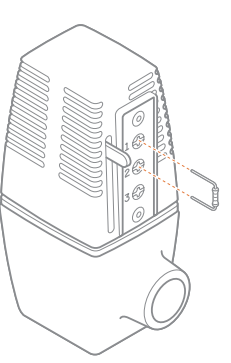
The thermostat displays “Power Resistor Required” on the screen
You have a system that requires the included power resistor to be installed on the zone valves on your HVAC equipment. See the diagram below for where to install the power resistor between terminals 1 and 2 on Taco valves.
Is my thermostat a repeater in the Z-Wave network?
The thermostat is only a repeater when it has been added to the network while it has a common wire connected and powered. If the thermostat receives a common wire after being added to the network, the thermostat will need to be removed and re-added to enable the repeater functionality.
Where do I view and change advanced features and settings for my thermostat?
Advanced thermostat configurations and features such as outdoor balance point, staging delays, venting (HRV, VRV, and air baffles), and Geo-Services require an online account and security panel or gateway. Use the Customer Website or Mobile App to configure these options.
My thermostat is displaying a fault code
Please contact your service provider. You can find their contact information on the Customer Website or Mobile App.
Resetting the thermostat to factory defaults
The thermostat can be reset back to its factory settings. This will reset all of the HVAC settings, rules, and schedules on the thermostat, and it will also remove the thermostat from the Z-Wave network.
NOTE: The panel or gateway will be unaware that this procedure was performed, so it is recommended that you follow the process in the “Remove the thermostat from the Z-Wave network” section before performing this reset.
- Press the MENU button.
- Select SETTINGS.
- Select INSTALLER.
- Select RESET.
The thermostat displays “Isolation Relay Required” on the screen
Please contact your service provider. You can find their contact information on the Customer Website or Mobile App.
Notices
FCC
This device complies with part 15 of the FCC Rules. Operation is subject to the following two conditions:
- This device may not cause harmful interference.
- This device must accept any interference received, including interference that may cause undesired operation.
This equipment has been tested and found to comply with the limits for a Class B digital device, pursuant to part 15 of the FCC Rules. These limits are designed to provide reasonable protection against harmful interference in a residential installation. This equipment generates, uses, and can radiate radio frequency energy and, if not installed and used in accordance with the instructions, may cause harmful interference to radio communications. However, there is no guarantee that interference will not occur in a particular installation. If this equipment does cause harmful interference to radio or television reception, which can be determined by turning the equipment off and on, the user is encouraged to try to correct the interference by one or more of the following measures:
- Reorient or relocate the receiving antenna.
- Increase the separation between the equipment and the receiver.
- Connect the equipment to an outlet on a circuit different from that to which the receiver is connected.
- Consult the dealer or an experienced radio/TV technician for help.
IC
Under Industry Canada regulations, this radio transmitter may only operate using an antenna of a type and maximum (or lesser) gain approved for the transmitter by Industry Canada. To reduce potential radio interference to other users, the antenna type and its gain should
be so chosen that the equivalent isotropically radiated power (e.i.r.p. is not more than that necessary for successful communication.
Z-Wave
This product can be operated in any Z-Wave network with other Z-Wave-certified devices from other manufacturers. All non-battery-operated nodes within the network will act as repeaters regardless of vendor to increase the reliability of the network.
NOTE: The grantee is not responsible for any changes or modifications not expressly approved by the party responsible for compliance. Such modifications could void the user’s authority to operate the equipment.
Questions?
Visit: www.alarm.com/supportcente or contact your service provider.8281 Greensboro Drive Suite 100 Tysons, VA 22102 © 2019 Alarm.com. All rights reserved. Designed in the USA by Building 36, an Alarm.com company. Made in China.
REFERENCE:
Download Manual: Alarm.com ADC-T3000 Smart Thermostat User Manual
https://device.report/energystar/2333422
Alarm.com ADC-T3000 Smart Thermostat – Energy Star Certification
OTHER MANUALS:
Alarm.com Adc-t3000 Smart Thermostat Installational Manual
Alarm.com ADC-T3000 Smart Thermostat Troubleshooting Guide
Alarm.com ADC-T3000 Smart Thermostat Operational Manual
![]()
Leave a Reply