TCS Bays Controls SZ1020 Series Programmable 7-Day Thermostat

Description
The SZ1022, SZ1031, and SZ1035, are microprocessor-based programmable thermostats designed for conventional heating and cooling applications. The SZ1022 features a 7-day time clock, while the SZ1031 and SZ1035 feature a 365-day time clock.
Features
- Stand-alone or network operation
- Adjustable delay on power-up and start-up for soft starts
- P+I control option
- Smart Recovery
- No battery backup required
- Built-in HVAC equipment protection
- 32 character LCD display
- 6 status LEDs
- Remote room sensing capability
- User setpoint adjustment limits
- Local and remote override capability
- System and fan switching with access lockouts
- Auxiliary time clock output (economizers)
- Equipment monitoring inputs and indication
- External time clock input
- Access to programming or schedule may be locked out or limited with the use of an access code
- Fahrenheit or Celsius temperature display
- Uses ZigBee protocol, IEEE 802.15.4 compliant*
- Self-healing, “plug & play” mesh network*
- 100mW output at 2.4 GHz*
- 150 to 500 feet typical in building range*
* wireless devices only
Mounting
The SZ1022, SZ1031, and SZ1035 are designed for wall mounting using two #6-32 machine screws sheet metal screws, either over a horizontally installed 2” x 4” junction box, or directly to block or drywall.
For best results, the thermostat should be mounted on an interior wall which reflects normal room environment, at a height of approximately five feet from the floor. Avoid areas exposed to direct sunlight, unusual heat or cool sources, open doors and windows, unventilated locations and hot or cold air from diffusers.
If using a remote room sensor, it should be mounted in the manner described above. The thermostat may then be mounted in an area which is accessible for adjusting its settings.
Caution: Remove power from thermostat prior to mounting.
Wiring
The SZ1022, SZ1031, and SZ1035 use standard terminal designations for wiring. See diagram below.
REMOTE TEMPERATURE SENSOR WIRING
Use 18 AWG shielded twisted-pair grounded at the sensor mounting location. Sensor wiring runs of up to 250 feet are attainable if properly shielded wire is used and the installation environment is free of electrical noise. Sensor wire should be kept at least five feet away from line voltage wiring.
The SZ1022 accepts two 2-wire remote sensors and the SZ1031 and the SZ1035 accept three. Consult the TS Series Temperature Sensor Submittal Data Sheet for a complete listing of packaging and application styles. When using TCS/Basys Controls three-wire sensors, use the black and red leads and either clip or twist off the white lead. Make sure that the dip switches are set for the sensors you are using.
POWERING THE SUPERSTAT
Superstats are powered from 24 VAC +/- 20%.
If wiring for communications, dedicated power must be used to power the Superstat. Several “S” Series thermostats may be powered from the same transformer, provided that the transformer has sufficient power. (Superstats require 8 VA @ 24 VAC.)
Caution: Do not connect to 120 VAC. When multiple TCS/Basys Controls devices are using a single transformer, the polarity of the power wiring must be maintained because all TCS devices are half-wave rectified and have common return paths.
When the Superstat is used as a stand-alone or wireless thermostat without communications, the unit transformer may be used to power it. To do this, install a jumper between the “R” and “+24” terminals. The “24-” terminal must then be connected to the common side of the unit transformer.
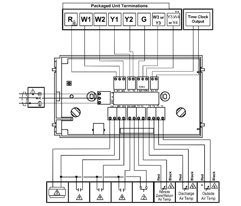
- For communication wiring, use twisted, shielded 18 AWG. Must be run separately.
- Dry momentary contact. Must not be powered.
*Not available with the SZ1022. - 24 VAC transformer. See powering instructions
- Dry contact. Must not be powered.
** Available only on SZ1035. For 3 Heat&3 Cool mode, B/O is W3 and Y/W4 is Y3. - Sensor input wiring 18 AWG, twisted, shielded pair.
- Up to nominal 28 VAC from equipment transformer.
Setup
Note: If using remote sensor(s), the calibration may need to be adjusted. See “Checkout and Troubleshooting” section.
TEMPERATURE SENSOR SELECTION
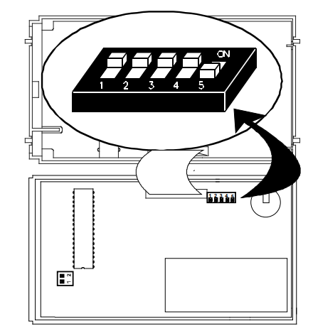
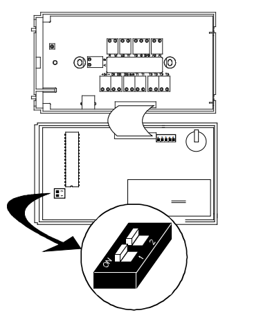
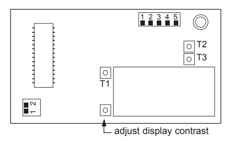
The dipswitches in the cover (shown above) must be set when using remote room, discharge, and/or outdoor sensors.
Use the following guide to determine the dipswitch settings for your application.
- Using built-in room sensor only. (This is the default setting.)
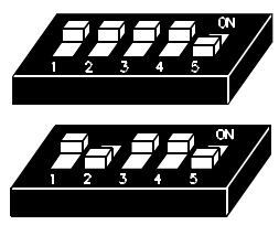
- Using built-in room sensor with discharge air sensor only.
- Using built-in room sensor with outdoor air sensor only.*
- Using built-in room sensor with both discharge and outdoor air sensors.*
- Using remote room sensor only.
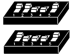
- Using remote room sensor with discharge air sensor only.
- Using remote room sensor with outdoor air sensor only.*
- Using remote room sensor with both discharge and outdoor air sensors.*
* (SZ1031 and SZ1035 only)
KEYPAD ACCESS
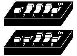
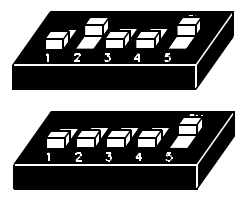
The dipswitches in the thermostat cover (shown above) must be set in order to lock the user out of the program and/or to set the clock and schedule. Use the guide below to set these dipswitches for your application. User access may also be limited with an access code set in programming. (The fan and system switches are enabled or disabled in programming only, and require no dipswitch placement.)
- Keypad access to both programming and clock setup. (This is the default setting.)
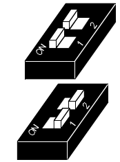
- No keypad access to programming or clock setup.
- Keypad access to programming only.
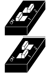
- Keypad access to clock setup only.
Once the dipswitches have been set and you have confirmed that the sensors are reading correctly (and program and clock setup are finished, if locking out access with dipswitches), secure the cover to the base with the two set screws located at the top right and the left side.
Programming
Programming
The SZ1022, SZ1031, and SZ1035 may be programmed through the keypad on the face, or with a PC.
If programming with a PC, the following must be set via the display and keypad prior to programming:
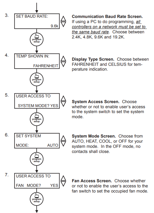
- Address (step #2)
- Baud rate (step #3)
- Temperature scale (step #4)
For more information on programming through the PC, consult your TCS software manual.
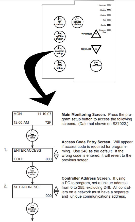
PROGRAMMING THROUGH THE KEYPAD
To access the programming screens, press the program setup button. To make changes, use the warmer and cooler keys. Access may be locked out with dipswitches, or an access code may be required.
Setting Clock & Schedule
The SZ1022, SZ1031, and SZ1035 clock and schedule may be set through the keypad and display, or with a PC. For more information on programming through the PC, consult your TCS software manual.
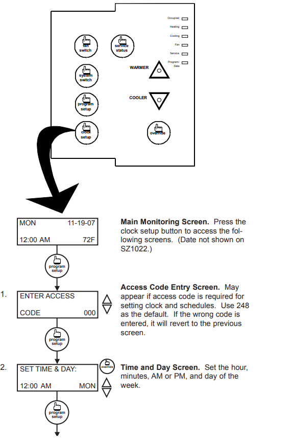
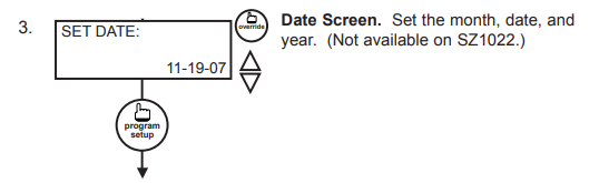
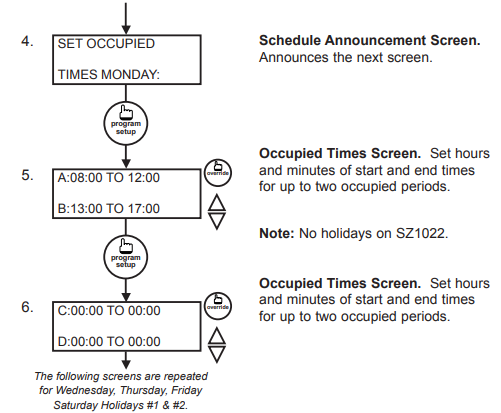
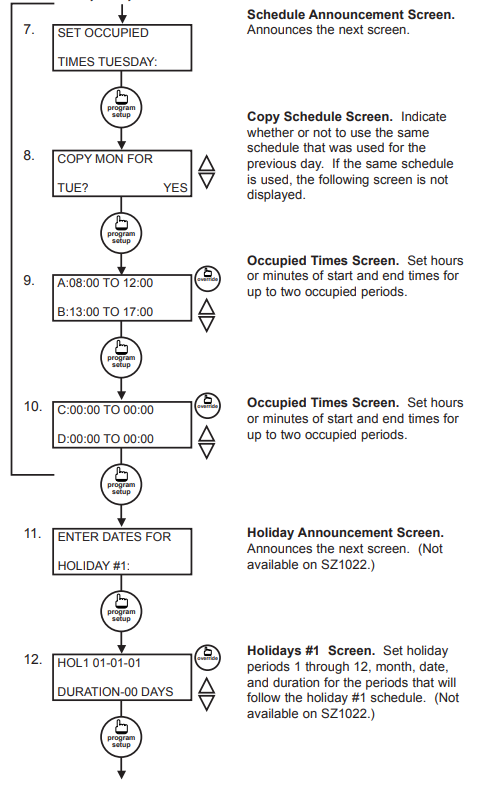
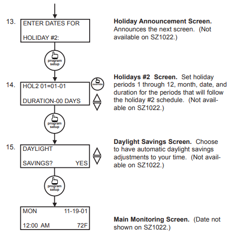
SETTING CLOCK & SCHEDULE THROUGH THE KEYPAD
To access the clock and schedule screens, press the clock setup button. To make changes, use the warmer and cooler keys. For screens that have more than one field to set, use the override key to move to the next field. Access may be locked out with dipswitches, or an access code may be required.
The SZ1022, SZ1031, and SZ1035 clock and schedule may be set through the keypad and display, or with a PC. For more information on programming through the PC, consult your TCS software manual.
SETTING CLOCK & SCHEDULE THROUGH THE KEYPAD
To access the clock and schedule screens, press the clock setup button. To make changes, use the warmer and cooler keys. For screens that have more than one field to set, use the override key to move to the next field. Access may be locked out with dipswitches, or an access code may be required.
Operation
UNOCCUPIED SETBACK
The SZ1022, SZ1031, and SZ1035 operate in either an occupied or unoccupied mode. During the occupied mode, the occupied heating and cooling setpoints will be maintained, and the fan will operate according to its occupied setting. During the unoccupied mode, the unoccupied heating and cooling setpoints will be maintained, and the fan will operate according to its unoccupied setting. The occupied LED will be lit when the unit is operating in the occupied mode.
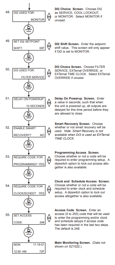
The occupied schedule may be set utilizing the internal time clock or DI3 may be used with an external time clock, where- as when DI3 is closed, the unit is in the occupied mode. The Smart Recovery function is disabled when DI3 is used for the external time clock.
OVERRIDE
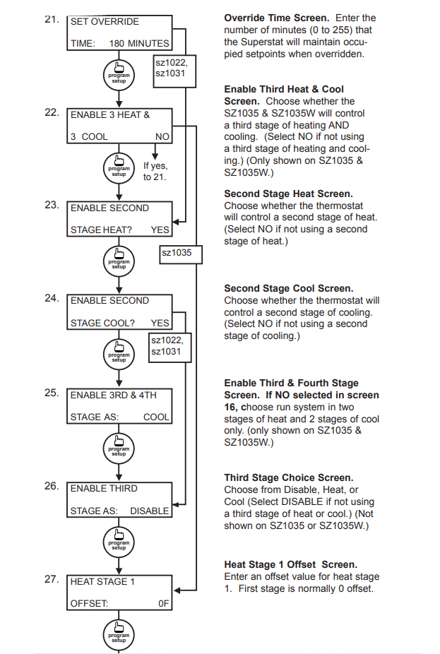
A timed override is available using the button on the face of the thermostat or through momentary contacts wired into the OVR terminal. The amount of time the unit will be overridden is set from 0 to 255 minutes in the programming screen. This override behaves differently depending on the mode the thermostat is operating in (occupied or unoccupied) and the options that have been enabled within the software. In standard mode, the override only activates in unoccupied mode and takes the thermostat into occupied mode. If “Override for Occupied Period” is enabled, the override also activates in occupied mode and takes the thermostat into unoccupied mode. In either case, you are able to view the time remaining in the override period both within the software and by using the service button to scroll through the status screens. If the occupant desires to return the thermostat to unoccupied or occupied operation (depending on how the override was used) before the time interval is up, they may press the override again. If “Continuous Occupied Override” or “Continuous Unoccupied Override” is enabled, then pressing the override once and then pressing and holding it for 5 seconds puts the thermostat into a “hold” mode (the override LED on the thermostat will flash quickly). In this mode, the override setpoints are used until the next occupied period is reached, or until the thermostat is manually taken out of the “Continuous Override” mode by pressing the override again.
Continuous override is available through the DI3 contact or the software. If DI3 is set to external override, the unit will be in occupied mode whenever the DI3 contact is closed. When using this option, the timed override may still be activated.
The software allows you to override the thermostat by putting the override parameter into the remote mode, and thus disabling the timed override.
SETBACK AND OVERRIDE APPLICATIONS
In most applications, it is desired to maintain a regular schedule, and allow timed override with the button on the face or with a remote momentary contact.
To allow a regular schedule, and also automatically override with the use of occupancy or light sensor, set DI3 to external override and set it up so that the contact is closed when you want the override.
For applications where a room might not be used on a regular schedule, such as conference rooms, set DI3 to external time clock and close the contact when you want the room occupied, such as with a switch or wind-up timer. If each occupancy period is about the same, (theaters, meetings) another option is to set the DI3 to external override, and use the timed override button to put the unit in occupied mode.
To make the unit always occupied, set DI3 to the external time clock and short the DI3 terminal to ground.
DISCHARGE AIR TEMPERATURE SENSING
The SZ1022, SZ1031, and SZ1035 accept a remote discharge air sensor for monitoring purposes. (See setup instructions for dipswitch placement for this option.)
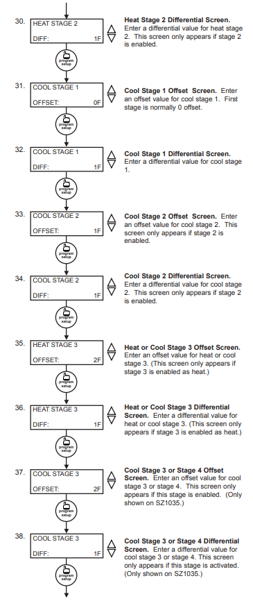
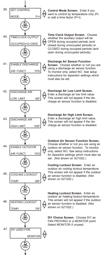
Choose YES in programming screen #35 only if you are using a discharge air sensor and you want to enable the discharge air temperature high and low limit functions. If NO is chosen, the discharge air will still be monitored.
When the function is enabled, a HIGH LIMIT and LOW LIMIT are entered in steps #36 and #37. If the HIGH LIMIT is reached, the fan and heating stages will be turned off and will remain off until the discharge air temperature falls 3° below that limit. If the LOW LIMIT is reached, the fan and cooling stages will be turned off and will remain off until the discharge air rises 3° above that limit. When either limit is reached, the service LED will be on until normal operation resumes.
The discharge air span is 0°F to 150°F (-17.8°C to 65.6°C).
OUTDOOR AIR TEMPERATURE SENSING
The SZ1031 and SZ1035 accepts a remote 1000 Ω outdoor temperature sensor for monitoring purposes. (See setup instructions for dipswitch placement for this option.)
Choose YES in programming screen #38 only if you are using an outdoor air sensor and you want to enable the outdoor air heating and cooling lockout functions. If NO is chosen, the outdoor air will still be monitored.
When the function is enabled, a COOLING LOCKOUT TEMP and HEATING LOCKOUT TEMP are entered in steps #39 and #40. If the outdoor temperature falls below the COOLING LOCKOUT TEMP, all cooling stages will be locked out and will remain locked out until the outdoor air temperature rises 2° above the lockout temperature. If the outdoor temperature rises above the HEATING LOCKOUT TEMP, all heating stages will be locked out and will remain locked out until the outdoor air temperature falls 2° below the lockout temperature.
The outdoor air span is -40°F to 160°F (-40.0°C to 71.1°C).
FAN PROVING
The SZ1022, SZ1031, and SZ1035 allow DI1 to be set for fan proving to protect equipment on fan failure. To utilize this function, input a pressure or current switch which tells when the fan is running. If the thermostat closes its fan contact, and the DI1 is not closed after thirty seconds, the system will go to OFF, disabling all outputs, the fan LED will turn off, and the service LED will be lit until the system is manually reset by switching the system to a mode other than OFF.
DI2 SETPOINT SHIFT
The SZ1022, SZ1031, and SZ1035 allow DI2 to be set for setpoint shift for energy demand setback. This is enabled by setting DI2 to the MONITOR mode. A digital contact that closes when setback is needed should be wired into DI2. You may specify a number of degrees such that, when the thermostat is operating in the occupied mode, and DI2 is closed, the heating setpoint will be lowered this number of degrees, and the cooling setpoint will be raised this number of degrees. The fan will continue to operate according to its occupied setting. If you are using DI2 as monitor for another purpose, make sure to set this value to zero.
STAGE OUTPUT PARAMETERS
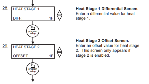
For each stage of heating and cooling, you may specify an offset and a differential value. This allows you to adjust the operation of the thermostat to fit your equipment to the building load. The offset value is the amount away from the setpoint a stage will turn off. By assigning a stage a value other than zero, you “anticipate” that the residual heat or cooling in the duct or the other stages will bring the temperature back to setpoint. In most cases, the first stage is set to zero. The differential value is the difference between the on and off points. This value depends on the load and on the equipment size. If the equipment is large for the load, you may want to make this value as high as 5 to prevent equipment cycling. If the equipment is small compared to the load, or if tight control is desired, you may want to make this value as low as 1.
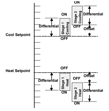
The fact that the stages are configurable allows unused stages to be set to activate physical alarms if desired.
In summary, unlike most other multi-stage programmable thermostats, the Superstat allows independent adjustments of “offsets” and “differentials” for stages of heating and cooling. The offset settings can be viewed as setpoints for the second and third stages and are programmed in the Superstat in the number of degrees (i.e. 1,2,3 … ) beyond the heating and cooling setpoints (temperatures to be maintained).
The differential for each stage can be viewed as the “anticipator” function used in mechanical thermostats.
Digital Input Summary Table
| DIGITAL
INPUT |
APPLICATION | LED
INDICATION? |
SERVICE SCREEN
(DI STATUS SCREEN) |
CONTROL
PROVIDED |
SENSOR OR
DEVICE NEEDED |
| DI1 | Fan Proving | YES | CHECK FAN, FAN OK
or FAIL |
YES – turns system mode to “off”
— requires manual re-start (set system to auto) |
Differential pressure or current switch |
| DI1 | Equipment Monitoring | NO | OK
(DI1 OPEN or CLOSED) |
NO | Dry contact, switch. Any type for monitoring and indication |
| DI2 | Service Alert | YES
(DI2 SERVICE OFF or ON) |
OK or CHECK DI2 | NO
for monitoring and indication |
Dry contact, switch. Any type |
| DI2 | Monitor with setpoint shift | NO | OK
(DI2 OPEN or CLOSED) |
YES – shifts setpoint by a programmed amount | Dry contact, switch. |
| DI2 | Cooling Lockout | NO | OK
(COOL LOCKOUT ON or OFF) |
YES – locks out 2nd and 3rd stage cooling | Dry contact, switch. |
| DI3 | Filter Service | YES | OK or CHECK FILTER (FILTER OK or CHECK) | NO | Differential pressure switch |
| DI3 | External Occupancy Override | NO | OK
(EXT OVER ON or OFF) |
YES – switches to occupied mode as long as contact is made | Dry contact such as twist timer, light switch, etc. |
| DI3 | External Time Clock Input* | NO | OK
(EXT TIMECLOCK ON or OFF) |
YES -input overrides thermostat* occupancy program | Dry contact; external time clock (TCS part SL1001a) |
- P + I OPTION
The SZ1022, SZ1031, and SZ1035 also have a P+I option. Without enabling this option, stages turn on and off based on temperature vs. setpoint alone, as described above. By enabling this option, you allow a time factor to be added. This is useful when you are forced to have a large differential due to equipment size. At times when the building load is low, the temperature could potentially sit a few degrees off setpoint for some time. With the time factor added, the thermostat would compensate for this, turning on the equipment even though the temperature had not reached the limits described above. - DI2 COOL LOCKOUT
DI2 may be set as cool lockout for operation with economizers. An outdoor temperature switch may be wired in such that when DI2 is closed, the second stage of cooling is disabled.
SMART RECOVERY
“Smart Recovery” may be enabled to insure occupant comfort while saving money. It takes the building load into consideration and ramps the setpoint when going from the unoccupied mode to the occupied mode. At the beginning of the occupied mode, the occupied setpoint will be reached, many times without the need for the second stage to come on. This feature is automatically disabled when DI3 is set to external time clock. - AUXILIARY OUTPUT
An auxiliary relay output is available to output a signal based on the occupancy status. It is commonly used with an economizer minimum position control, or to signal an outdoor air damper to open in occupied times in lieu of an economizer. It may also be used for lighting or hot water heaters. Keep in mind that although it is an isolated relay (separate common terminal), it is rated at 24 VAC. For loads that exceed this, use an external relay. It may be set to be open (NO) or closed (NC) when the thermostat is operating in the occupied mode, and will be the opposite during the unoccupied mode. - BUILT-IN DELAYS
The SZ1022, SZ1031, and SZ1035 have delays built into the programming sequences to protect equipment. The fan has a minimum on and off time of 30 seconds. When the fan is in AUTO mode, it will come on 30 seconds before the heating or cooling stages are allowed to sequence on, and remain on for 2 minutes after the heating or cooling stages sequence off. Each stage has a minimum on and off time of two minutes. There is a minimum of two minutes between when one stage turns on until the next stage is allowed to turn on, as well as when one stage turns off until the next stage is allowed to turn off. - DELAY ON POWER UP
The SZ1022, SZ1031, and SZ1035 have an adjustable delay on power up. When several thermostats are used at one location, and the power goes out, most thermostats turn all of the units back on at the same time on regain of power, creating a peak. The thermostat allows you to set a value, in seconds, where no outputs are allowed to turn on for that length of time on power up. Setting each unit to a different delay allows you to soft start your system, and thus prevent this peak. Note, this delay is also applied to the start of occupied time. - DAYLIGHT SAVINGS TIME
Beginning in 2007, Daylight Saving Time (DST) in the U.S. will be extended by having an earlier change to DST in spring and a delay in switching back to standard time in fall. However, this change may only be temporary, as this “new” schedule is only in effect for a 2 year trial period. After that, the DST schedule may revert back, stay the same, or be something completely different. Products shipped starting in 2007 with firmware version 1.5 or higher accommodate the new DST schedule. Products shipped starting in 2008 with firmware version 2.0 or higher accommodate the new DST schedule and have the ability to be programmed to accommodate any future schedules that may be used. Should the schedule change and you need to customer program the DST start and end dates, simply enable the “Daylight Savings Time” option within the software and enter the starting month + week and the ending month + week.
Checkout & Troubleshooting
CHECKOUT
Note: The fan has a minimum on and off time of 30 seconds. The heating and cooling stages have a minimum on and off time of 2 minutes.
You may verify the status of heating and cooling stages and fan in monitoring screens #5, #6, and #7, which are accessed by pressing the SERVICE STATUS button.
- Verify all wiring prior to powering the thermostat.
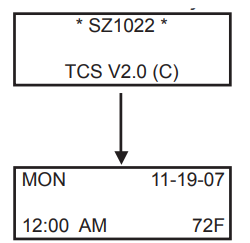
- Turn power on. The thermostat will display a momentary screen with the model number, and then the main monitoring screen with the time, day, date (SZ1031 and SZ1035 only), and current temperature.
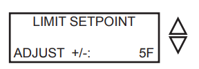
- Press the PROGRAM SETUP button until you reach screen #14 which allows you to set the occupant setpoint adjustment limits. Change this to +/-20 °F (11.1 °C). Press the PROGRAM SETUP button once more to store the change. Then press the SERVICE STATUS button once to exit the programming.
- Press the FAN SWITCH button to access the fan mode and change the mode to AUTO. Press the FAN SWITCH button once more to store the change. Press the SYSTEM SWITCH button to access the system mode and change the mode to AUTO. Press the SYSTEM SWITCH button once more to store the change.
- Verify that the thermostat is operating in the occupied mode by making sure that the top LED is lit. If not, press the OVERRIDE button. The LED should light up.
- Take note of the current temperature reading. Press the WARMER (up) button. The setpoint adjustment screen should now be showing. Press the WARMER button until the heating setpoint is greater than the current temperature by at least five degrees. The fan will come on. The heating stage(s) will sequence on after 30 seconds.
- Press the cooler (down) button until the heating setpoint is one degree less than the current temperature. The heating stage(s) will sequence off. The fan will turn off 2 minutes after the last heating stage.
- Press the cooler button until the cooling setpoint is less than the current temperature by at least five degrees. The fan will come on. The cooling stage(s) will sequence on after 30 seconds.
- Press the warmer button until the cooling setpoint is greater than the current temperature by one degree. The cooling stage(s) will sequence off. The fan will turn off 2 minutes after the last cooling stage.
- Go back to programming step #14 and set the setpoint adjust limit back to the desired value. Make any other changes in programming, clock, and schedule. Set the fan and system modes to their desired settings.
- If using remote sensors, verify that the reading is correct. If not, see Wrong Temperature Display in the Troubleshooting section.
No Display
Check for 24 VAC on terminals “+24” and “-24”. Check ribbon cable connecting the cover to the base for a good connection.
Fan Does Not Come On
The fan is on whenever the fan LED is on. If the fan should be on, but the fan LED is off, check the fan (FAN SWITCH button) and system modes (SYSTEM SWITCH button), and the unoccupied fan mode in programming. If the fan is off but the fan LED is on, check wiring. Short terminals “R” to “G” and see if the fan comes on. This is a check for a mechanical relay failure.
Heating or Cooling Does Not Come On
At least one stage of heating is on whenever the heating LED is on, and at least one stage of cooling is on whenever the cooling LED is on. If heating or cooling should be on but the heating or cooling LED is off:
- Check the fan and system switch modes.
- Check the heating and cooling setpoints.
- Check the room temperature to be sure heating or cooling should be on.
- Check the offsets and differentials.
- If using outdoor air or discharge air high and low limits, check their values to be sure heating or cooling is allowed.
If heating or cooling is off, but the corresponding SED is on, check the wiring. Short terminals “R” to “W1”, “W2” “Y1”,Y2”, or “G” and see if the heating, cooling, or fan comes on. This is a check for a mechanical relay failure.
Wrong Temperature Display
Initially, verify the wiring connections to check for problems (poor connections, opens, or shorts). If the temperature is at a minimum or maximum reading, check that the sensor dipswitch positions are correct as shown in the Setup section of this document. Also, verify the resistance reading for the sensor in question. A remote sensor should read 1080 to 1090 ohms at room temperature. The built-in sensor should read 108 to 109 ohms at room temperature. If any of the temperatures are still reading slightly high or low, you can add in a temperature offset (calibration) using Ubiquity or TCS Insight. In Ubiquity, you can edit the calibration offset for each temperature input (room, discharge, outdoor air, etc.) on the controller’s programming page. For example, if the room temperature is reading 2 degrees high, you would subtract 2 from the existing offset in the room temperature calibration offset field and submit the page. In TCS Insight, the process is similar. Refer to the Calibrate Using TCS Insight Tech Bulletin # 1019 for details. As a last resort and only when directed to do so by TCS technical support, you may be able to use the onboard adjustment pots. Refer to the Thermostat Sensor Calibration Tech Bulletin # 1005 for details.
Service LED is On
If the service LED is on, it may be for monitoring purposes or it may indicate a critical problem. The first monitoring screen, which is used to indicate why the light is on, can be accessed by pressing the SERVICE STATUS button.
Outputs Will Not Shut Off
First check room temperature and setpoints to determine whether the output should be on. There are delays and minimum on and off times for the fan and heating and cooling stages. Also, check the service status menus to verify that the outputs are on. Turning the system to “off” will instantly turn all outputs off. The thermostat can be reset by pressing the system switch button and the service status button simultaneously.
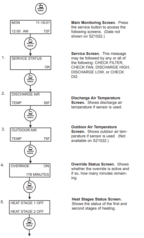
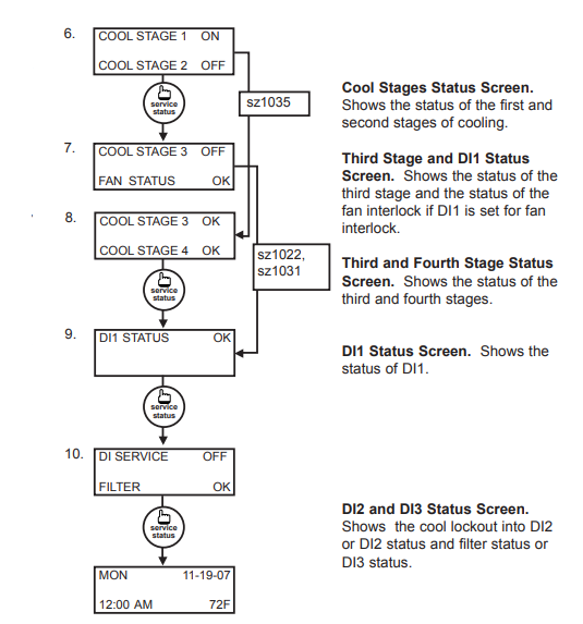
SERVICE SCREENS
Through repeated pressing of the SERVICE
STATUS button, the service screens (shown below) are displayed, which enables you to monitor various functions of the Superstat.
LED Description
Six LEDs on the face allow the occupant to view the current operating status of the thermostat.
- OCCUPIED
This LED will be lit whenever the unit is operating in the occupied mode. - HEATING
This LED will be lit when any heat output is closed. - COOLING
This LED will be lit when any cooling output is closed. - FAN
This LED will be lit when the fan output is closed. - SERVICE
This LED will be lit when the high or low discharge air limit has been reached, when the fan interlock has indicated failure, or when the filter service or service input are closed. - PROGRAM/DATA
This LED will be lit when the thermostat is within the programming or clock setup menus. It will blink when the unit is being accessed by a PC.
Additional monitoring is available by continually pressing the service key.
Limiting Occupant Access
- SETPOINT ADJUSTMENT
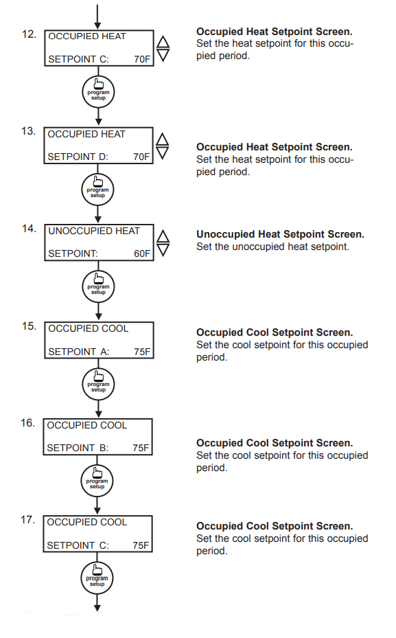
The occupant may temporarily change the occupied heating and cooling setpoints +/- 5’F by factory default. This setpoint change will remain until the end of the current occupied period, at which time the program reverts to the setpoints defined in programming. To change the range of adjustment allowed, see programming step # 14. - OVERRIDE
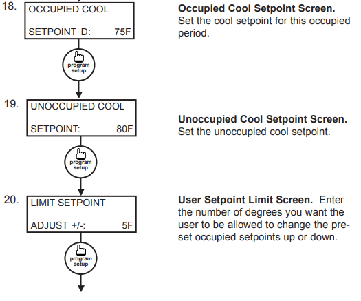
The occupant has the ability to put the unit into occupied mode by pressing the override button on the front. By factory default, the unit will remain in the occupied mode for 180 minutes. This value may be changed from 0 to 255 minutes in programming step #15. - FAN SWITCHING
The option to allow the occupant to change the occupied fan mode is allowed by factory default. To lock out access to fan switching, see programming step #7. - SYSTEM SWITCHING
The option to allow the occupant to change the system mode is allowed by factory default. To lock out access to system switching, see programming step #5. - SETTING CLOCK & SCHEDULE
The ability to set the clock and schedule is allowed by factory default. An access code may be required as set in programming step #43, or access may be denied altogether using dipswitches described in the setup section. - PROGRAMMING
The ability to program control parameters is allowed by factory default. An access code may be required as set in programming step #42, or access may be denied altogether using dipswitches described in the setup section.
User’s Guide
Inside the hinged door of the thermostat is the Superstat™ User’s Guide. This guide is designed to assist the installer in explaining to the user how to operate their new thermostat, as well as serve as a handy future reference for the user.
We recommend the installer fill out the appropriate pages in the User’s Guide and explain to the user how the thermostat operates, what settings may be changed, and how the time clock schedules are used.
REFERENCE
Download PDF
TCS Bays Controls SZ1020 Series Programmable 7-Day Thermostat User Manual
OTHER MANUALS:
TCS Bays Controls SZ1020 Series Programmable 7-Day Thermostat Product SPECIFICATION GUIDE
![]()
TCS Bays Controls SZ1020 Series Programmable 7-Day Thermostat User Manual