
Johnson Controls T5000 LCD Digital Fan Coil Thermostat
Application
- TSOOO series thermostats are designed to on/off control the fans and valves in air conditioner applications via comparison of the room temperature and setting temperature as reaching the aim of comfort and saving energy.
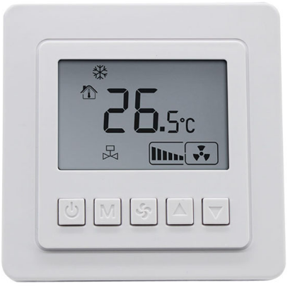
- TSOOO are microprocessor based thermostat with LCD display. It shows the following items: working states (cool/heat/ventilation), fan speed, room temperature, setting temperature. TSOOO features with one on/off button
 , one mode button (M), one fan speed selection button (+), two adjustment buttons
  .
.
Figure 3: T5200-TB/TF-9JR0/S0 Series Thermostat Dimensions in (mm)
- Prior to installation, please read the instructions.
- Incorrect wiring of line voltage and low voltage may damage the product.
- Any quality issue caused by incorrect wiring is not covered by warranty or return policy.
Installation
Install the T5000 where the occupant can read the display and adjust the setpoint easily. Situate the thermostat where the temperature is representative of the general room conditions. Avoid installing the T5000 near cold or warm air drafts, radiant heat, on an outside wall, or in direct sunlight.
Mounting
- Mount the T5000 Series thermostat to a 75x75x35mm standard electrical wall box. (See Figure 4)
- Follow the instruction in Removing the Base and then proceed to the Wall Mounting and the Wiring sections.
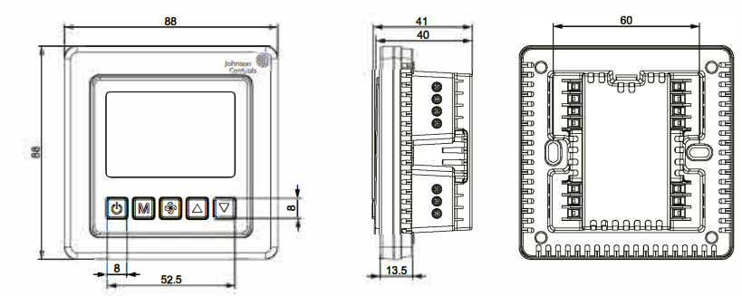
Note: All TSOOO Series models require two M4x25 mounting screw (not included) .
Wallbox Mounting
- To mount the TSOOO Series Thermostat:
- Pull the external field wiring from the wall through the rectangular opening in the base. Fasten the base to the wallbox using the appropriate two holes, as shown in Figure 2 and Figure 3, and two M4 x 25 screws.
- Proceed to the Wiring section for the correct configuration for the application and units.
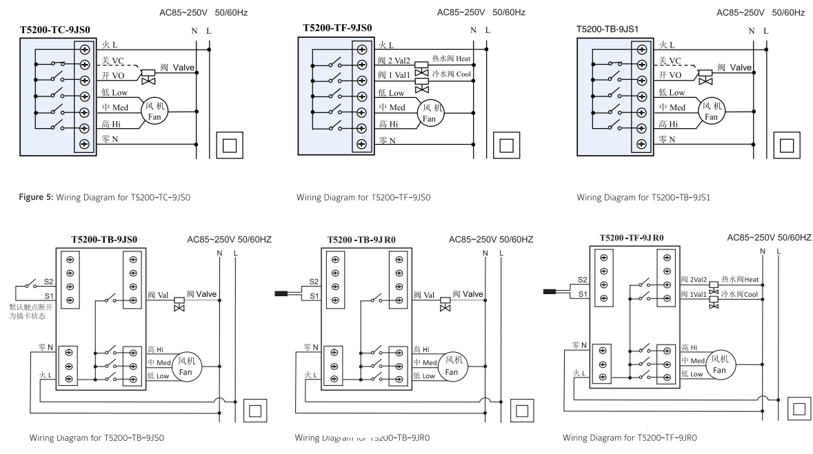
Wiring
Wire the unit according to the instructions for the appropriate model.
Note: When wiring the TSOOO Series Digital Fan Coil Thermostat, use wire nuts to finish and isolate each connection.
When the wiring is completed:
- Push the connected wiring through the rectangular hole in the base into the wallbox space.
- Hook the thermostat to the hinge at the bottom of the base and gently slide the thermostat down into position on the mounting base.
- Tighten the retention screw .
- Proceed to the Setup and Adjustment section to establish the desired settings. Wiring terminal designations and connections for typical applications appear in Figure 5.
Check-Out Procedure
After the installation, observe the complete operation cycles for cooling and heating control. This is to make sure that all control devices are functioning correctly. If the device is not working properly and the wiring is correct, the thermostat should be replaced by contacting your nearest Johnson Controls® Representative.
Instructions
- On/off: press “
 ” to turn on, press again to turn off, close the fan and valve.
 - Setting temperature: Press either
 buttons to increase or decrease by o. s’c.
 - Mode selection: press “M” to change the working mode,
 cooling,
  heating,
 ventilating. (no heat mode for T5200-TC-9JSO)
 - Fan speed selection: press to choose the speed 1
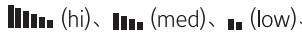 , AUTO (auto).
Under “AUTO” mode, the fan-speed will be changed automatically. Auto LOWspeed when the difference between room temperature and set-point exceed 1 °C, Auto MED-speed when exceed 2°C, Auto HI-speed when exceed 3 °C. - Valve Control: under cool (heat) mode, the valve will be open while the difference between room temperature and setpoint exceed 1 °C; while the room temperature reaches setpoint, the valve is closed with the fan still running.
Time-On and Time-Off Operation
- Hold down the “M” button for 3 seconds will enter the Timer On-Off setting. When the
 “
“ and “hh” of” hh mm” appear, press
 keys to set the time duration . To confirm setting, press Mi button once, press other keys to cancel the setting.
Press “M” button again, and “mm” of” hh mm” appear, press keys to set the time duration. Set time duration to “–“, to cancel the setting. After one cycle for Time-on and Time-off the setting will be automatically canceled.
Lock function
- Lock function: The thermostat will be locked automatically after 30 seconds under the lock function. Hold down the fan key 5 seconds to unlock.
Unoccupied energy-saving mode (T5200-TB-9JSO)
- Unoccupied energy-saving mode (by entrance card): While entrance card is pulled out, the temperature automatically set to 26°C, fan is on LO-speed if the thermostat is in cool mode; the temperature set to 18°C, fan is on LO-speed if in heat mode.
Low Temperature protection setting
- On power Off status and when room temperature is lower than 5°C, heat function will be automatically switched on,
 appears, the fan is set to HI-speed and the valve (heat valve for T5200-TF-9JSO, T5200-TF-9JRO) is opened. When the room temperature reaches 7 °C, the setting will be automatically canceled.
 - On power Off status, press “M” and keep 5 seconds, display “OF” or “On”, press
 to adjust the parameter. “OF” means cancelling low temperature protection, “On” means the protection function is on. Factory setting is “OF”.
Remote Temperature sensor (T5200-TB-9JRO, T5200-TF-9JRO) When remote sensor is connected, the built-in sensor will be disable.
Functional Code Setting Table
Enable the setting table: hold down the![]() for 5 seconds, “01” and code appear, after which press ‘M’ button to select code, use
for 5 seconds, “01” and code appear, after which press ‘M’ button to select code, use ![]() buttons to adjust the value.
buttons to adjust the value.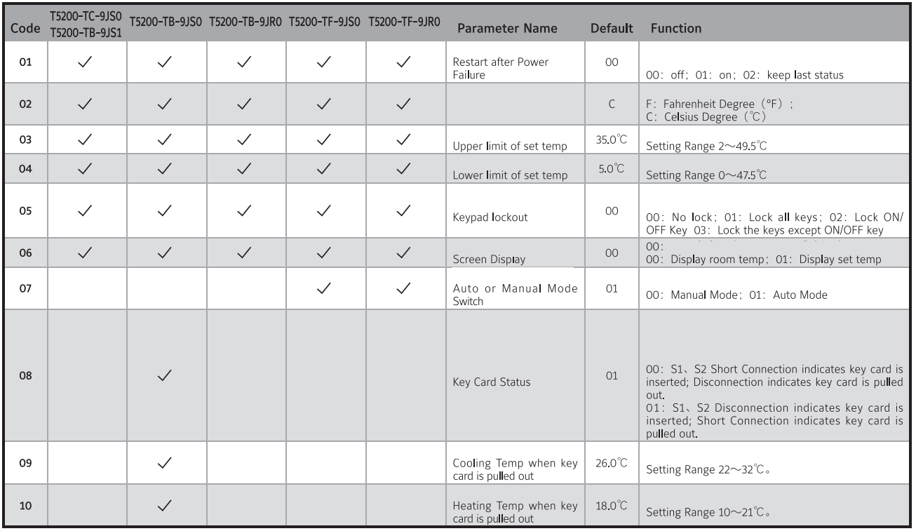
Power failure memory supports “restart” or “recover to previous status” after power resume
Temperature setting
If customers hope the displayed temperature higher or lower than the real temperature, operate as follows:
- On power off status, press both keep 5 seconds, display “XX °C” (no working mode display), press adjust the temperature, auto-confirmed after 6 seconds.
Alarm
- When the sensor is in fault, thermostat will close the fan and valve, display
 “El” and “E2”.
- El: Sensor short cut alarm
- E2: Sensor circuit breaker alarm
Display “HI”, temperature> SS°C; display “LO”, temperature< 0°C
Troubleshooting
After a power outage, the thermostat mode and all settings return as most recently used or set.
Repair and Replacement
Do not attempt to repair the TS000 Series thermostat. In case of an improperly functioning control, contact the nearest Johnson Controls’” representative, and specify the desired product code number. When contacting the supplier for a replacement please state the type/model number of the control located on the data plate or cover label.
Specifications
Refer to Product Catalog for Details.
IMPORTANT
- Use this TS000 Series Line Voltage Fan Coil Thermostat only as an operating control. Where failure of malfunction of the TS000 Series Thermostat could lead to personal injury or property damage to the controlled equipment or other property, additional precautions must be designed into the system. Incorporate and maintain other devices such as supervisory or alarm systems or safety or limit controls intended to warn of, or protect against, failure or malfunction of the TS000 Series Thermostat.
- Do not install this thermostat in condensing, wet, or damp environments . Moisture may cause damage to the thermostat.
- Do not remove PCB from the enclosure cover. Removing the PCB from the enclosure cover voids the product warranty.
- Make all wiring connections in accordance with local, nation, and regional regulations. Do not exceed the TS000 Series thermostat’s electrical ratings.
WARNING:
- Disconnect power supply before making electrical connections. Contact with components carrying hazardous voltages can cause electrical shock and may result in severe personal injury or death.
- Risk of Electrical Shock Ground the thermostat according to local, national, and regional regulations. Failure to ground the thermostat may result in electrical shock and severe personal injury and death.
- Risk of Electrical Shock and Property Damage Insulate and secure each unused wire lead before applying power to the thermostat. Failure to insulate and secure each unused wire lead may result property damage, electrical shock, and severe personal injury or death.
CAUTION: Do not apply power to the system before checking all wiring connections. Short circuited or improperly connected wires may result in permanent damage to the equipment.
Description of Hazardous Substances and Content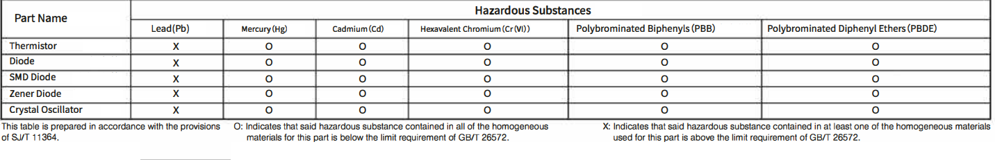
REFERENCE:
DOWNLOAD MANUALS:
Johnson Controls T5000 LCD Digital Fan Coil Thermostat-Installation Instructions
![]()
Johnson Controls T5000 LCD Digital Fan Coil Thermostat-Installation Instructions
Leave a Reply