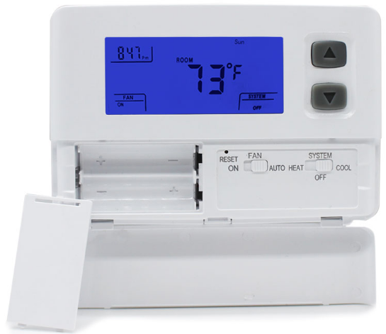
Hotowell HTW-ST01-A Non-Programmable THERMOSTAT
Identify System Type
1 Heat / 1 Cool single stage thermostat.Non Programmable, Compatible with heat pump system
This thermostat is compatible with the following systems
- Gas, oil, Propane or electric furnace
- Central air conditioner
- Geo Thermal / Hot water system with or without pump
- Millivolt system
- Central heating and cooling system
- Heat pump without auxiliary/backup heat
- Forced Air / In-Floor Radiant / Radiator system
Features
- ºF or ºC configurable
- Child Lock Function
- Large LCD display, Backlight.
- Heat and Cool set point storage.
- Display of room temperature, set temperature and current time simultaneously.
- Fan switch ON and AUTO.
- Permanent user setting retention during power loss. No batteries are required.
- Apply to 24VAC or 2 *AA alkaline batteries power supply.
- Air Filter change Indicator, Low Battery Indicator, Temperature calibration.
- 4- or 5-wire compatible (C is optional for non-heat pump systems)
- Manual Changeover / Fan Switch, Easy operation friendly.
- Mercury-Free, Environmentally Safe
- Built-in compressor protection
Specification
| Power Supply | 20VAC-30VAC 50-60HZ or Battery powered. |
| Terminal Load | 1.0A per terminal, 3.0A maximum total load |
| Set Point Temp. Range | 45ºF to 90ºF (7ºC to 32ºC). |
| Accuracy | +/- 1ºF or +/- 0.5ºC. |
| Dimensions | 6.0” W X 4.7” H X 1.1” D/152.5x120x28mm |
| Color | White |
| Installation Hole Distance | 3.37”/85.5mm Horizontal and 3 1/4”(83 mm)Vertical
or 2.36”/60mm Horizontal |
Display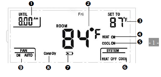
- Time
- Room Temperature
- Setting Temperature
- Heating
- Cooling Output
- Heat/Off/Cool Mode Indicate
- Low Battery Indicate
- Compressor Timing Delay
- Fan Status
Installation
Remove Old Thermostat
- Turn Off the Power
 warning: To prevent electrical shock and/or equipment damage, disconnect electrical power to the system at the main fuse or circuit breaker box, or by flipping a switch at the air handler. Do not restore power until installation is complete.
To ensure the power to your heating and cooling system has been turned off, try to turn on heating or cooling by changing the temperature on your old thermostat - Remove the old thermostat cover
Remove the old thermostat’s front cover from the wall base. Some covers pull off easily, while others may need to be removed by prying the cover off with a screwdriver.
CAUTION: Your old thermostat may have a sealed glass tube containing mercury. Be careful not to damage the tube or dispose of the tube in your trash. - Label wires
Tip: Taking a picture with a camera or smartphone can help you not only remember how wires are connected to the terminals, but can also ensure that you label your wires correctly.- Using your screwdriver, carefully unscrew one wire at a time from the terminal block and attach the corresponding wire label sticker.
- Please note that not all terminals may be used, and that there’s no standard color code for thermostat wires, so your wire colors may vary.
- For your reference, we’ve included a terminal label reference chart as below to help you connect the wires in your old thermostat to your new thermostat in case you get stuck.
Terminal labeling reference chart
| If your current terminal has the following letter | Label the wires with the following letters |
Terminal function |
| RC | RC | 24V Power (Cooling) |
| RH, R, R5, 5 | RH | 24V Power (Heating) |
| C | C | 24V (Common) from Equipment Transformer |
| W, W1, 4 | W | Heating Relay |
| Y, Y1 | Y | Cooling Relay |
| G | G | Fan Relay |
| O | O | Reversing Valve
(for heat pump applications energized in Cool mode) |
| B | B | Reversing Valve
(for heat pump applications energized in Heat mode) |
Identify jumper wire
|
On your old thermostat, if… |
Then, on your new thermostat… |
| Terminal RC and RH are connected with a jumper wire |
Leave the jumper wire in its place |
| There’s only one R wire (RC, RH, R or R5) coming out of the wall |
Leave the jumper wire in its place |
| Terminal RC and RH (or 5 or R5) are NOT connected by a jumper wire |
Remove the jumper wire between RC and RH |
For terminal Y and W:
If you have a heat pump with reversing valve, connect Y and W with a jumper wire on your new thermostat.
Remove old thermostat base
With all of your wires disconnected and properly labeled, you may now safely remove the thermostat base from your wall.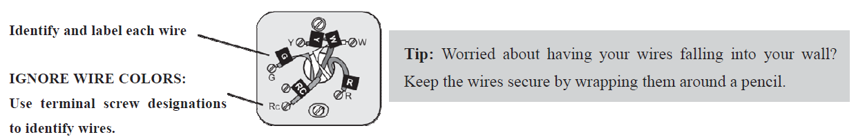
Mounting and Wiring Your New Thermostat
- Install new thermostat base
Mount your new thermostat base using screws. Drill holes and insert wall anchors to secure the thermostat base to the wall, if necessary.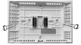
- Connect wires to corresponding terminal blocks
Match each labeled wire to it’s corresponding terminal on the mounted thermostat base. Insert each labeled wire into the hole of it’s matching terminal, and using the screwdriver, tighten the screw on the terminal block securely.
CAUTION: Your old thermostat may have a sealed glass tube containing mercury. Be careful not to damage the tube or dispose of the tube in your tras - Set switch and advanced wiring

- Install the batteries and attach front cover
Install 2*AA alkaline batteries and push the front cover on to the thermostat base until it’s secure. - Turn on power
Turn on your power at the source.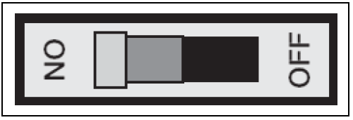
Congratulations
You’ve completed the thermostat installation process
Check Thermostat Operation
Fan operation
If your system does not have a G terminal connection, skip to 5.2 Heating system.
- Move FAN switch to ON position. The blower should begin to operate.
- Move FAN switch to AUTO position. The blower should stop immediately.
Heating system
- Move SYSTEM switch to HEAT position. If the heating system has a standing pilot, be sure to light it.
- Press 5 to adjust thermostat setting room temperature. The heating system should begin to operate.
- Press 6to adjust temperature setting below room temperature. The heating system should stop operating.
Cooling system
CAUTION: Take care when securing and routing wires so they do not short to adjacent terminals or rear of thermostat. Personal injury and/or property damage тау оссиг. - Move SYSTEM switch to COOL position.
- Press
 to adjust thermostat setting below room temperature. The blower should come on immediately on high speed, followed by bold air circulation.
 - Press
 to adjust temperature setting above room temperature. The cooling system should stop operating.
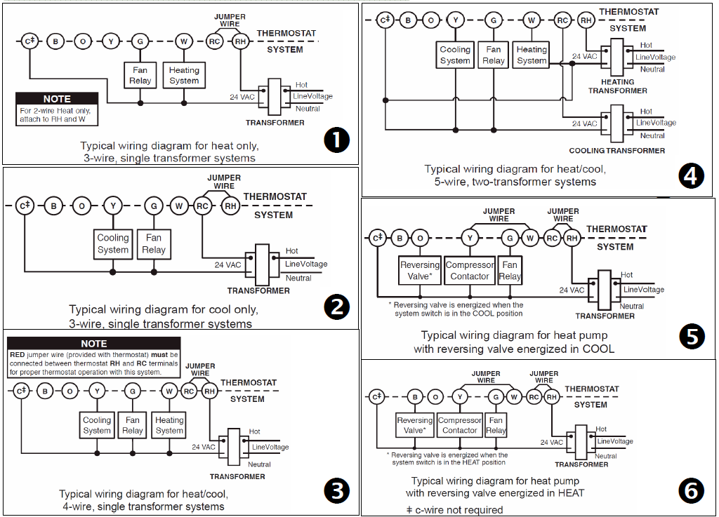
Typical Wiring Diagram
Thermostat Operation
Setting the temperature
- Set the SYSTEM switch to either HEAT or COOL, then press the ▲ or ▼ button until the temperature you want to maintain is shown on the right side of the display. If you want to turn the system off, just
- move the SYSTEM switch to the OFF position and the FAN switch to the AUTO position.
Clock setting
- Move the SYSTEM switch to the OFF position, then press and hold the ▼ buttons for 5 seconds to enter the clock setting mode. The display will show the HOUR setting first . Use the ▲ button to select each user setting. Press the ▼ button to shift to the next menu item ( MINUTES,WEEK DAY).Use the ▲ button to select each user setting also.
- Move the SYSTEM switch to the HEAT or COOL position to exit the setting menu. If no buttons are pressed within 15 seconds , the thermostat will exit the configuration menu.
Filter review
- Move the SYSTEM switch to the HEAT or COOL position, then press and hold the ▲ and ▼buttons for 5 seconds to review filter running days.To exit the review menu press the ▲ or ▼ buttons one time. Or
- If no buttons are pressed within 15 seconds, the thermostat will exit the configuration menu.
- In review mode, press and hold the ▲ and ▼ 15 sec. to clean the filter warning. It will show “dEF” blink.
Child Lock
- Quickly and simultaneously press the and three times to lock the temperature adjustment, and again to unlock.
RESET function. ▲ ▼
- This function can help operator to recovery system when fault happened, display out of order or system halted. Please use a pin to insert in button RESET hole till sounded click, then loosen it.
Configuration Menu
The configuration menu allows you to set certain thermostat operating characteristics to your system or personal requirements. It is also called as ISU(Installation Set-Up) process.
Move the SYSTEM switch to the OFF position, then press and hold the ▲ and ▼ buttons for 5 seconds to enter the configuration menu.
The display will show the first item in the configuration menu. Press the ▼ button to shift to the next menu item. Use the ▲button to select each user setting. To exit the configuration menu and return to normal operation, move the SYSTEM switch to the HEAT or COOL position. If no buttons are pressed within 2 minutes, the thermostat will exit the configuration menu. The configuration menu chart summaries the configuration options. An explanation of each option follows.
| Step | Press Buttons | Displayed (Defaults) | Select by ▲ or▼ | Description |
|
1 |
▲ & ▼ 5 seconds |
CC (FA) |
FA or SL |
Select (FA)st or (SL)ow
cooling cycles, Default = FA-Note 1 |
| 2 | ▼ | HC (FA) | FA or SL | Select F(ast) or (S)low Heating cycles. Default = FA-Note 1 |
|
3 |
▼ |
HO (0) |
0 or 1 |
Select system heating type:
0 = Gas, oil, or electric heating. 1 = Heat pump heating. Default = 0 |
|
4 |
▼ |
bL (2) |
1 – 3 |
Select display backlight :
(1) = OFF. (2) = 30 seconds on any button push. (3) = ON. Default = 2. Option (3) can be activated only if the common is used. -Note 2 |
|
5 |
▼ |
FL (00) |
00, 1 thru12 |
Select filter time in months. Default = 00.
A selection of “00” deactivates the filter feature. -Note 3 |
| 6 | ▼ | FC (F) | F or C | °F or °C display. Default = F |
|
7 |
▼ |
CL (0) |
+4 TO -4 |
Select temperature calibration point up to 4° higher or 4°lower.
Default = 0 |
|
8 |
▼ |
CP (5) |
0 or 5 |
Compressor Lockout delay. 0 = none, 1= 1 Min
2=2 Min 3=3 Min 4=4 Min 5 = 5Min Default = 5 -Note 4 |
Notes:
- The FA setting is used to produce shorter Heating/Cooling cycles. The SL setting produces a longer Heating/Cooling cycle. Both settings produce very accurate temperature control and can be set to your personal preference. FA cycles the system at a 0.5ºF (0.5ºC) differential, and SL cycles the system at 1.5ºF (1.5ºC).
- When operated from batteries only, the LCD display backlight will be illuminated less than 5 seconds after each button pressed, options (2) & (3) will operate the same when terminal “C” is not connected.
- The thermostat will display the Filter Alarm after a set time of operation. This is a reminder to change or clean your air filter. This time can be set from 0 to 12 months in 1 month increments. Selection of 00 WILL CANCEL THIS FEATURE. When Filter Alarm is displayed, you can clear it by pressing the and buttons. This resets the timer and starts counting the days until the next filter change.
- Select compressor lockout delay 0,1,2,3,4,5 To protect the compressor from short cycling, you can select compressor off-time cycle between 0 to 5 minutes. When the thermostat compressor time delay occurs, the Cool On or Heat On display will flash during compressor lockout.
Important Safety Information
- Always turn off power at the main power source by removing the fuse, or switching the circuit breaker to the off position before installing, removing, cleaning, or servicing this thermostat.
- Use this thermostat only as described in this manual. Read all of the information in this manual before installing this thermostat.
- Use a professional personnel/installer to install this thermostat.
- This is a 24VAC low-voltage thermostat, do not install on voltages higher than 30 vac.
- ALL wiring must conform to local and national building and electrical codes and ordinances.
- Do not short (jumper) across terminals on the gas valve or at the system control to test installation.
This will damage the thermostat and void the warranty. - Do not switch the system to cool if the temperature is below 50ºF (10ºC). This may damage the air conditioning system.
- Replace batteries when the battery icon indicates a low battery message.
- Change the Air Filter when the Filter Change Icon begins blinking.
REFERENCE:
DOWNLOAD MANUALS:
Hotowell HTW-ST01-A Non-Programmable THERMOSTAT Installation and Operation Manual
![]()
Hotowell HTW-ST01-A Non-Programmable THERMOSTAT Installation and Operation Manual