
Savant CLI-W200 Smart Thermostat

What’s in the Box
- (1) Wi-Fi Thermostat (CLI-W200x)
- (1) Installation Kit
- (2) Drywall Anchors (039-0328-xx)
- (2) #6 x 3/4 inch Pan Head Screws (039-0327-xx)(1) Sheet of Wire Labels (080-0096-xx)
- (1) Quick Start Guide (this document)
Specifications
| Environmental | ||
| Temperature | 32 to 104 F (0 TO 40 C) | |
| Humidity | 10% to 90% (non-condensing) | |
| Standards | ||
| Wireless | Wi-Fi (802.11 b/g/n 2.4 GHz)
IMPORTANT! 802.11r fast roaming is not supported. |
|
| Security | 70 mA typical, 250 mA maximum | |
| Max Power | 6 watts | |
| Power | ||
| Input | 24V AC | |
| Current Draw | 70 mA typical, 250 mA maximum | |
| Max Power | 6 watts | |
| Cable Requirements | ||
| Power | #18 AWG | |
| HVAC | #18 AWG Thermostat Wire (solid) | |
| Remote Sensors | #24 AWG – 500 feet (152 m) max | |
| Regulatory | ||
| Safety / Emissions |  |
FCC Part 15 |
| FCC ID: | ASU-CLIW200 | |
| IC: | 10052A-CLIW200 | |
| RoHs | Compliant | |
Optional Sensors
- SST-TEMP1 Remote Temperature (Flush Mount)
- SST-OTEMP1 Remote Temperature (Outdoor)
- CLI-THFM1 Temperature and Humidity (Flush Mount)
- CLI-PLEN1R/C Plenum Sensor
- CLI-SLAB1 Slab Sensor 009-1593-02
Welcome
This document describes how to:
- Remove the old thermostat.
- Mount your new CLI-W200 thermostat.
- Wire your new CLI-W200 thermostat.
Getting Started
The following is needed for a trouble free installation: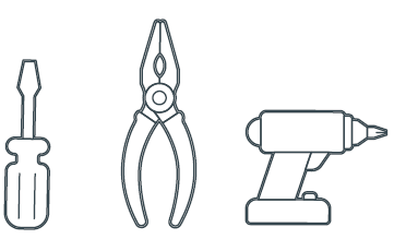
- Pencil
- #2 Phillips screwdriver
- Small slotted screwdriver
- Drill with 5/32 inch drill bit
- Wire stripper
- Needle-nose pliers
- Hammer (if wall anchors are used)
CAUTION! When replacing an older thermostat that contains Mercury in a sealed tube, do not discard into trash. Refer to the thermostat-recycle.org website for information on how to properly dispose.
Location and Mounting Overview
For new installations or when relocating the thermostat, follow the guidelines below:
- Locate thermostat on an inside wall.
- Do not locate where air circulation is poor such as in a corner or behind a door.
- Do not locate near windows or doors to reduce the expo-sure to drafts.
- Install away from any heating conditions such as direct sunlight, near a radiator register or vent, or near a fireplace.
- To adhere to ADA requirements, install thermostat 48 – 54 inches (1.22 – 1.37 meters) above the floor.
- Height requirements can be adjusted upward to 60 inches (1.5 meters) if ADA requirements are not mandatory.
- The thermostat does not need to be level to operate cor-rectly. Leveling the thermostat is for aesthetics only.
- Thermostat can be oriented in either a portrait or land-scape layout.
Remove Old Thermostat
- Before starting the process, scroll through the old thermo-stat and record the current settings and schedules.
- Switch OFF power at either the breaker panel or the switch that controls your HVAC system.
- Open the old thermostat so the wiring is accessible. Take a photo of the existing thermostat and wiring. The photo should reveal wire colors and terminal designations.
- Using chart below, add a check and record the wire color for each power wire. Not all terminals may be populated.
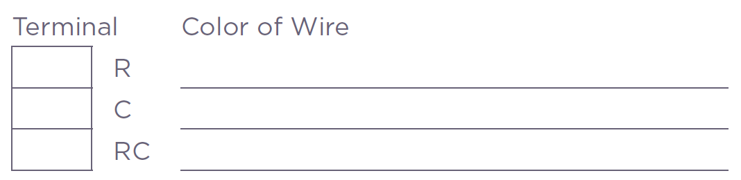
- Remove each of the wires recorded above and attach a label that matches the terminal designation from the old thermostat. Label wires according to the terminal desig-nation and NOT the wire color.
- Again, using the chart below, add a check and record the wire color for each signal wire.
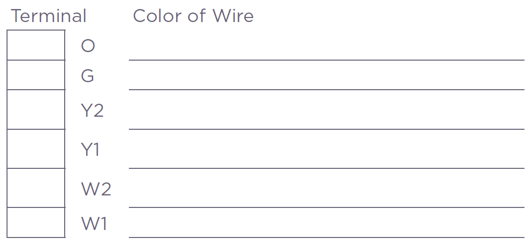 NOTE: Additional information on terminal designations and useful wiring diagrams are available in the CLI-W200 Thermostat Deployment Guide located in the pages of the Savant Customer Community.
 - With a screwdriver, remove the wires from each terminal.
TIP: Wrap wires around a pencil or similar to prevent the wires from falling back into wall. - Remove the old thermostat from the wall.
Install Thermostat Mounting Plate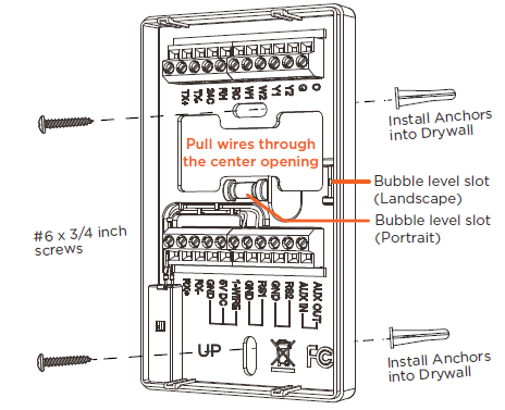
- To separate the thermostat from its mounting plate, grasp the mounting plate in one hand and the thermostat in the other (Grasp the end opposite the proximity sensor).
- Rock the top and bottom halves until they separate.
- Position the thermostat mounting plate onto the wall. With a pencil, mark the two mounting holes onto the wall (See image above).
- When mounting using a portrait layout, use the bubble level installed in the center of the mounting plate to level.
- When mounting using a landscape layout, remove bubble level by pushing it out through the rear of the mounting plate and reinstall it into the bubble level slot on the right side of center cutout. See diagram above.
- Drill a 5/32 inch hole on each mark made and tap the wall anchor into wall until flush. In some installations that have a sub wall to fasten to, wall anchors may not be required.
- Pull the existing wires through the center cutout in the mounting plate.
- Screw the mounting plate to the wall using the supplied #8 x 3/4 inch screws.
Making Connections
When connecting wires to the CLI-W200, follow the guide-lines set below to ensure a safe and secure connection.
- With small slotted screw- driver, turn the screws on connector counterclock-wise (CCW) until silver crimps open enough to slide wire(s) into square slots.
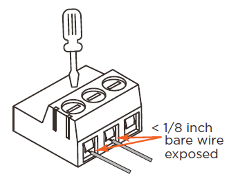
- Strip back insulation on each wire to 1/4 inch and insert the stripped wire into the proper connection.
- Turn screws clockwise (CW) until the crimps tighten around each wire. Tug on each wire a bit to verify they are secure.
Connecting Power
The CLI-W200 does not run on batteries and requires a separate power source to operate. To power the thermostat, a voltage must be applied to the RH and 24C terminals. If only the power wires removed were from the R and C terminals of the old thermostat (See Remove Old Thermostat section above), use the diagram below to make connections.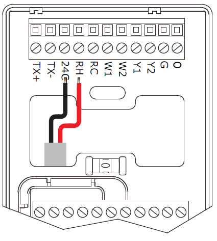
- RH – Connect the wire removed from R termi-nal of old thermostat to the RH terminal. On a new install, RH connects to the 24V AC wire from the HVAC transformer.
- 24C – Connect the wire removed from the C (common) terminal on old thermostat to the 24C terminal.
On a new install, 24C connects to the common wire from the HVAC transformer.
Additional Powering Schemes
If the HVAC system uses separate power sources to run the heating and cooling, you should have three wires labeled for power (R, C, and RC). In this scenario, remove the jumper shunt from JP1. The next section describes this.
Jumper Shunt – JP1
Jumper JP1 on the thermostat board connects the RH and RC terminals. The thermostat is shipped from the factory with a jumper shunt installed. For systems with more than one power source, remove the jumper shunt.
- RH: Supplies power to the relays connected to terminals W1, W2, and O.
- RC: Supplies power to the relays connected to terminals Y1, Y2, and G.
- 24C: Common terminal. The common (C) wire from HVAC system is required for thermostat to run.
HVAC Wiring
Use the table below to connect the signaling wires from the HVAC system. Depending on the type of system installed in your home will determine which wires are connected. In some installations, only the power wires described in the previous sections are required.
TIP: Refer to the Making Connections section above to ensure a safe and secure connection is made.
Temperature Sensors
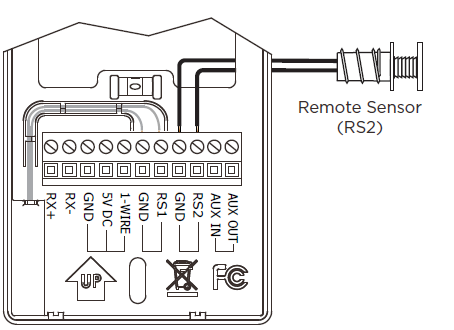
There are connections for two temperature sensors.
- RS1 – The main temperature sensor. This sensor is shipped already pre-installed between terminals RS1 and GND
- RS2 – A remote temperature sensor can be added between terminals RS2 and GND. No polarity is observed on either sensor.
Smart Sensor Connection
A 1-wire humidity/temperature (CLI-THFM1) sensor that sup-ports measuring both humidity and temperature can also be added to the system. Connect the sensor to the 1-Wire, 5V DC, and GND terminals as shown in diagram below.

Network and Configuration Requirements
With the thermostat installed and wired, it can now be added to the local network and once communicating with the Savant Pro System Host an HVAC configuration can be created and uploaded to the Host. Locate the CLI-W200 Thermostat De-ployment Guide available on the Savant Customer Communi-ty to finish installation of the thermostat.
Network Configuration
To ensure the IP Address will not change due to a power outage, Savant recommends DHCP reservation be configured. Using this method, static IP Addresses for all devices can be managed from a single User Interface, avoiding the need to access devices individually. Setting DHCP reservation varies from router to router. Refer to the documentation for the router to configure DHCP reservation.
Additional Information
- CLI-W200 Thermostat Deployment Guide (009-1636)
- SST-TEMP1 Remote Indoor Temp Sensor QRG (009-0800)
- SST-OTEMP Remote Outdoor Temp Sensor QRG (009-0989)
- CLI-THFM1-xx Temp and Humidity Sensor QRG (009-1064)
- CLI-SLAB1 Slab Sensor QRG (009-1097)
- CLI-PLEN1R Residential Plenum Sensor (009-1096)
- CLI-PLEN1C Commercial Plenum Sensor (009-1100)
Frequently Asked Questions
Does the CLI-W200 require batteries?
No, the CLI-W200 is powered using the power from the HVAC system. If no common (C) wire was removed from the old thermostat, a common wire must be added.
How does CLI-W200 get software updates?
Software is updated Over The Air (OTA). Whenever an update is available on the Savant Cloud, the update will take place automatically. The CLI-W200 must be connected to a local network that has WAN access for the updates to occur.
Will CLI-W200 still work if the Wi-Fi connection is lost?Yes, most thermostat functions will still function when not connected to Wi-Fi. However, functions such as schedules and OTA updates can not occur.
My thermostat was received damaged. What should I do?
If the thermostat was purchased through a contractor or retailer, contact the contractor or retailer to return it. If ther-mostat was purchased from the Savant Store, contact Savant through the Savant Customer Community.
Are both Fahrenheit and Celsius supported?
Yes
Does the thermostat support measuring humidity?
Yes, Savant offers a 1-wire smart sensor (CLI-THFM1) that measures both humidity and temperature.
Does the thermostat support setting both a heating and cooling set point?
No, The CLI-W200 thermostat is a single set point thermo-stat. However, the thermostat does support adding a +/- range to the set point. For example, adjusting the set point to 70° with a range of +/- 3° will manage the temperature so it stays between 67° and 73°.
FCC Statement
Regulatory
The following statements are applicable to the CLI-W200x
This device complies with part 15 of the FCC Rules. Operation is subject to the following two conditions:
- This device may not cause harmful interference, and
- This device must accept any interference received, including interferences that may cause undesired operation.
This equipment has been tested and found to comply with the limits for CLASS B digital device, pursuant to Part 15 of FCC Rules. These limits are designed to provide reasonable protection against harmful interference when the equipment is operated in a residential installation. This equipment generates, uses and can radiate radio frequency energy and, if not installed and used in accordance with the instructions, may cause harmful interference to radio communications, However, there is no guarantee that interference will not occur in a particular installation. If this equipment does cause harmful interference to radio or television reception, which can be determined by turning the equip-ment off and on, the user is encouraged to try correct the interference by one or more of the following measures:
- Reorient or relocate the receiving antenna.
- Increase the separation between the equipment and the receiver
- Connect this equipment into an outlet on a circuit different from that to which the receiver is connected.
- Consult the dealer or experienced radio/TV technician for help.
Radiation Exposure Statement
This equipment complies with FCC radiation exposure limits set forth for an uncontrolled environment. This equipment should be installed and operated with a minimum distance 20cm between the radiator & your body.
FCC Caution: Any changes or modifications not expressly approved by the party responsible for compliance could void the user’s authority to operate this equipment. This transmitter must not be co-located or operating in conjunction with any other antenna or transmitter.
FCC and IC Identifier for Savant Thermostat
This device electronically displays the FCC declaration of conformity logo as well as the FCC and IC identifier. This information can be found on the device by accessing:
HVAC Mode menu ![]() 00 Swipe
00 Swipe ![]() Left About.
Left About.
Industry Canada Statement
This device complies with Industry Canada license-exempt RSS standard(s). Operation is subject to the following two conditions:
- This device may not cause interference, and
- This device must accept any interference, including interference that may cause undesired operation of the device.
- This Class B digital apparatus complies with Canadian ICES-003.
- This device and its antenna(s) must not be co-located or operating in conjunc-tion with any other antenna or transmitter, except tested built-in radios. The County Code Selection feature is disabled for products marketed in the US/Canada.
Radiation Exposure Statement
This equipment complies with IC radiation exposure limits set forth for an uncontrolled environment. This equipment should be installed and operate with minimum distance 20cm between the radiator and your body.
© 2018 Savant Systems, LLC,
QR SCAN
For product information
Address: 45 Perseverance Way, Hyannis Ma. 02601
Telephone: 508.683.2500
Savant.com
04/13/2018
Reference
Download Manual:
Savant CLI-W200 Smart Thermostat QUICK START GUIDE
Leave a Reply