
Io-HVAC-controls UT32 Programmable Touchscreen Thermostat
INTRODUCTION
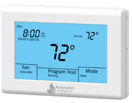
The UT32 Titan is a feature-rich touchscreen thermostat that can be battery-powered or hardwired to the HVAC equipment. Using a common sense approach to the installation will ensure this product is installed properly and to the customer’s satisfaction. Please take time to read and understand this manual so that installation and testing is performed in an efficient manner. This manual is to be used in conjunction with the supplied User Manual. Although great care has been taken in the preparation of this manual, iO HVAC Controls takes no responsibility for errors or omissions contained herein. It is the responsibility of the installer to ensure that this thermostat and the equipment connected to it operate in a safe and efficient manner. Due to ongoing product improvements, iO HVAC Controls reserves the right to change the specifications of the UT32 Titan thermostat or its components without notice.
GETTING STARTED
As with any HVAC project, careful installation is the key to a successful outcome. Time taken during the installation process will be rewarded with fewer callbacks. The steps required to install the UT32 Titan thermostat are as follows.
- Read and understand this Installation Manual and User Manual.
- Mount and wire the sub-base.
- Install the batteries.
- Set the 4 system switches to match the equipment application.
- Wire optional remote temperature sensor(s).
- Power the thermostat.
- Set the Advanced Installer settings.
- Test the thermostat.
INSTALLING THE THERMOSTAT
DISASSEMBLY
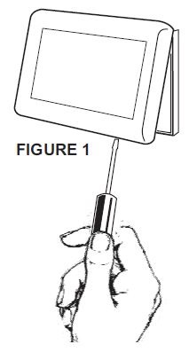
There are two release slots located on the bottom of the thermostat. Gently push the flat blade of a small screwdriver into one slot at a time and pry upward until the catch disengages. Carefully swing the thermostat upward and away from the sub base. (Figure 1)
THERMOSTAT LOCATION
The thermostat should be installed in a location that represents the ambient space temperature. Do not install the thermostat in an area where drafts are present, near the floor, behind doors or on an external wall. Avoid placing the thermostat in areas where the air movement is limited, affected by direct sunlight or other areas not typical of the temperature in the space.
MOUNTING THE SUB BASE
When mounting the thermostat subbase, be aware that drafts may travel down wall cavities and enter the back of the thermostat through the control wire hole in the wall. It is important to seal the hole to prevent any drafts that might affect the internal temperature sensor
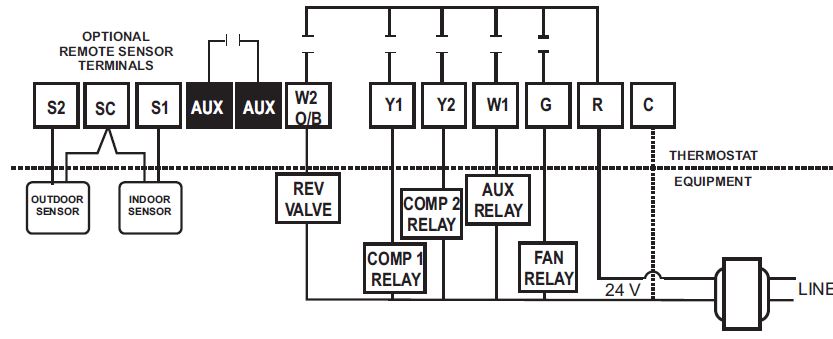
Pull the control wires through the large opening in the thermostat subbase. Next, level and mount the subbase on the wall using the supplied anchors and screws. (Figure 2) Do not over-tighten the mounting screws as the subbase may warp causing the improper seating of the thermostat connecting pins to the terminal blocks. Use a properly sized screwdriver and back each screw terminal out (counterclockwise) before landing each wire to its dedicated terminal. Do not over-tighten the terminal screws. Check to ensure that all wires are landed correctly and dressed properly to prevent any shorts. Refer to the Typical System Wiring Diagrams in this manual for proper wiring
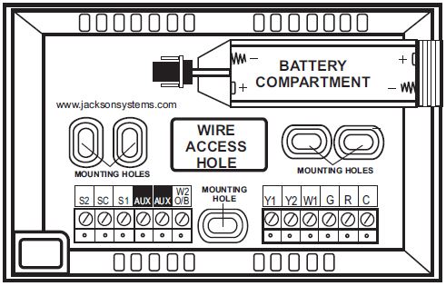
TERMINAL DESIGNATIONS
| TERMINAL | DESIGNATION |
| S2 | Outdoor Sensor |
| SC | Sensor Common |
| S1 | Indoor Sensor |
| AUX | Auxiliary Contacts |
| W2/OB | Second Stage Heat or Reversing Valve |
| Y1 | First Stage Cool or First Stage Compressor |
| Y2 | Second Stage Cool or Second Stage Compressor |
| W1 | First Stage Heat/Auxiliary/Emergency Heat |
| G | Fan |
| R | 24 VAC Hot |
| C | 24 VAC Common |
TERMINAL DESIGNATIONS
SETTING THE SYSTEM SWITCHES
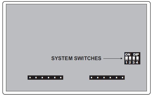
The thermostat contains a set of four system switches located on the thermostat printed circuit board. (Figure 3) The switches are used to match the thermostat operation and relay outputs with the HVAC system requirements. Refer to the system switch functions on the next page to properly configure the thermostat
SYSTEM SWITCH FUNCTIONS
- Switch 1 – Equipment Type Switch 1 sets the equipment type. For conventional heat/cool equipment, set the switch to the OFF position (factory default). For heat pump equipment set the switch to the ON position.
- Switch 2 – Fan or Reversing Valve
- When Switch 1 is OFF
- For gas heat, set the switch to the OFF position (factory default). For electric heat, set the switch to the ON position.
- When Switch 1 is ON
- For ‘O’ reversing valve, set the switch to the OFF position. (factory default) For ‘B’ reversing valve, set the switch to the ON position.
- Switch 3 – Equipment Stages
- Switch 3 sets the number of equipment stages.
-
- OFF = 1 heat / 1 cool gas/electric or 2 heat / 1 cool heat pump or dual fuel.
- ON = 2 heat / 2 cool gas / electric or 3 heat / 2 cool heat pump or dual fuel.
-
- Switch 3 sets the number of equipment stages.
- Switch 4 – Dual Fuel Mode
- For conventional heat pump equipment, leave switch 4 in the OFF position (factory default). For dual fuel equipment, set switch 4 to the ON position
INSTALLING THE BATTERIES
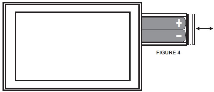
The thermostat comes with two AA batteries. Even if the thermostat is hardwired, battery backup is recommended to maintain the real-time clock in the event of a power failure. All other memory is non-volatile in the event of battery or primary power loss. Press in on the battery access compartment and slide the drawer out. Install the two AA batteries matching the + and – orientation. Push the battery compartment in until it clicks shut. When the batteries are properly installed, the touchscreen display will light up. (Figure 4)
WIRING DIAGRAMS
TYPICAL SYSTEM
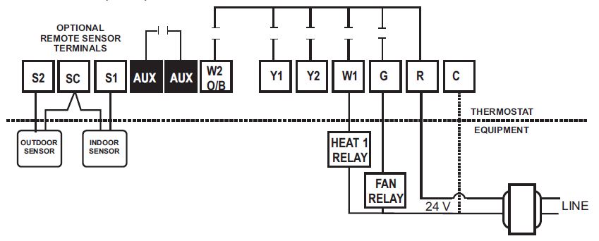
HEAT ONLY (GAS)
- Switch Settings
- Switch 1 = OFF Heat/Cool
- Switch 2 = OFF Equipment controls fan on call for heat
- Switch 3 = OFF Single Stage
- Switch 4 = OFF Leave OFF
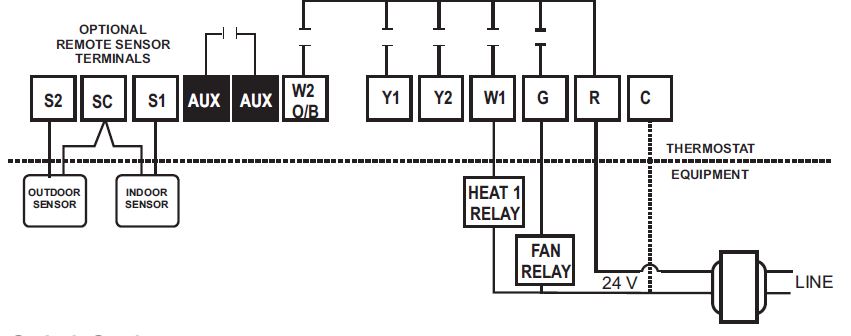
HEAT ONLY (ELECTRIC)
- Switch Settings
- Switch 1 = OFF Heat/Cool
- Switch 2 = ON Thermostat controls fan on call for heat
- Switch 3 = OFF Single Stage
COOL ONLY (SINGLE OR MULI-STAGE)
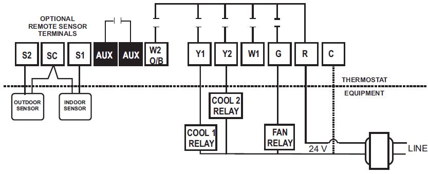
- Switch Settings
- Switch 1 = OFF Heat/Cool
- Switch 2 = OFF Fan energized on call for cooling
- Switch 3 = OFF/ON OFF = Single Stage ON = Multi-stage
- Switch 4 = OFF Leave OFF
1 HEAT/1 COOL (GAS)
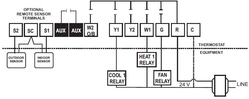
- Switch Settings
- Switch 1 = OFF Heat/Cool
- Switch 2 = OFF Fan energized on call for cooling
- Switch 3 = OFF Single Stage
- Switch 4 = OFF Leave OFF
2 HEAT/2 COOL (GAS)
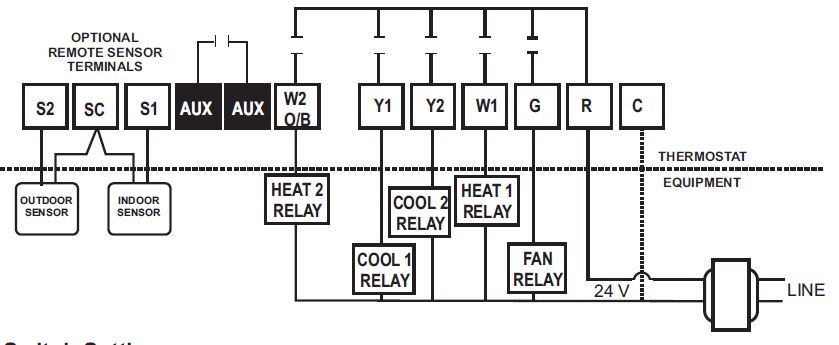
- Switch Settings
- Switch 1 = OFF Heat/Cool
- Switch 2 = OFF Fan energized on call for cooling
- Switch 3 = ON Multi-stage
- Switch 4 = OFF Leave OFF
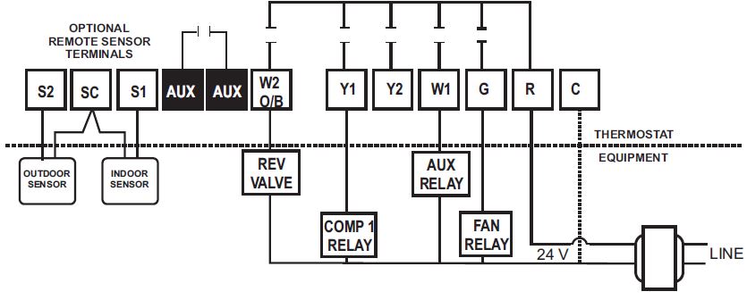
2 HEAT/1 COOL (HEAT PUMP)
- Switch Settings
- Switch 1 = ON Heat Pump
- Switch 2 = OFF/ON OFF = ‘O’ ON = ‘B’
- Switch 3 = OFF 2 Heat / 1 Cool HP
- Switch 4 = OFF Leave OFF
3 HEAT/2 COOL (HEAT PUMP
- Switch Settings
- Switch 1 = ON Heat Pump
- Switch 2 = OFF/ON OFF = ‘O’ ON = ‘B’
- Switch 3 = ON 3 Heat / 2 Cool HP
- Switch 4 = OFF Leave OFF
2 HEAT/1 COOL (DUAL FUEL)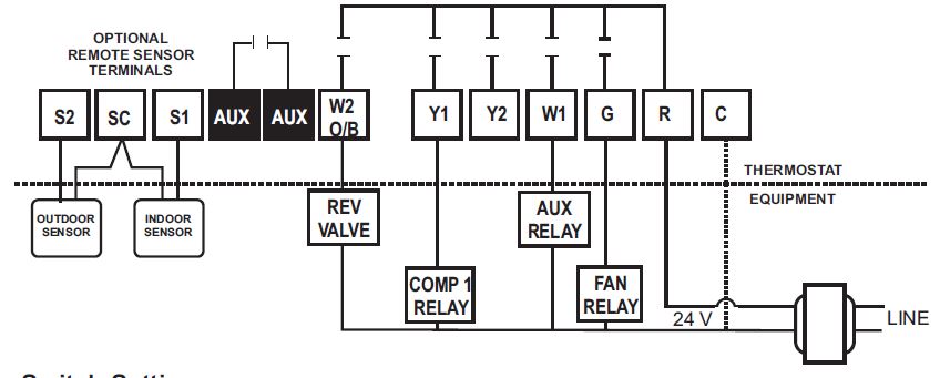
- Switch Settings
- Switch 1 = ON Heat Pump
- Switch 2 = OFF/ON OFF = ‘O’ ON = ‘B’ Reversing Valve
- Switch 3 = OFF 2 Heat / 1Cool dual fuel
- Switch 4 = ON Locks out heat pump when the furnace is energized
3 HEAT / 2 COOL (DUAL FUEL
Switch Settings
Switch 1 = ON Heat Pump
Switch 2 = OFF/ON OFF = ‘O’ ON = ‘B’ Reversing Valve
Switch 3 = ON 3 heat / 2 cool dual fuel
Switch 4 = ON Locks out the heat pump when the furnace is energized
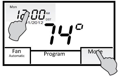
ENTERING THE SETUP MENU
Tap the display to bring the backlight on then press and hold both the Clock and Mode section for 5 seconds to enter the Installer Menu.
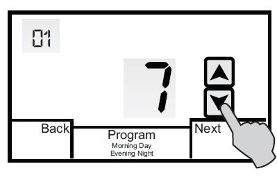
SELECTING THE PROGRAMMABLE OR NON-PROGRAMMABLE OPERATION
The first menu 01 selects programmable or non-programmable operations. Press the UP or DOWN arrows to change the selection. The factory default is 7.
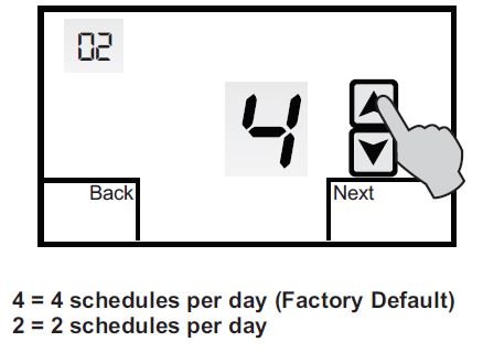
SELECTING THE NUMBER OF PROGRAM SCHEDULES (ONLY DISPLAYED WHEN 01 = 7)
If menu 01 is set to 7, the thermostat can be configured for 4 or 2 schedules per day. The factory default is 4.
SELECTING MODE
Menu 03 selects the mode of operation. The factory default is 0.
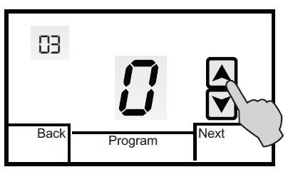
- = Auto-changeover (Heat/Cool/Auto/Off for Heat/Cool) (Heat/Cool/Auto/EHeat/Off for Heat Pump (Factory Default)
- 1 = Manual Changeover (Heat/Cool/Off) or (Heat/Cool/E.Heat/Off)
- 2 = Heating Only (Heat/Off) or (Heat/E.Heat/Off)
- 3 = Cooling Only (Cool/Off
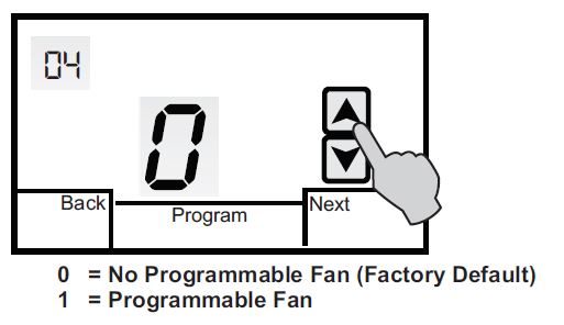
SELECTING PROGRAMMABLE FAN
Menu 04 selects the Programmable Fan option which allows selecting continuous or auto fan operation for each program event when the Programmable mode is selected. The factory default is 0.
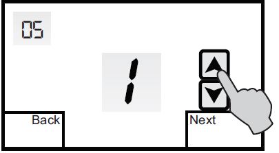
ASSIGNING AUXILIARY CONTACTS
Menu 05 assigns the auxiliary dry relay contacts (AUX) as Normally Open or Normally closed when the Programmable Fan Option 04 is ON. Whenever Programmable Fan is in the Always On mode (constant ventilation) for a selected program period, the relay contact will go open or closed based on the auxiliary relay option selection. The auxiliary contacts are also used to open an outside air damper when Timed Ventilation is selected. (See details on page 55 and 56)
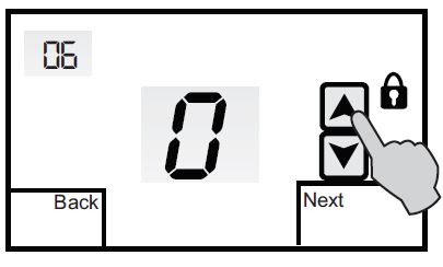
SELECTING TOUCHSCREEN LOCK OPTIONS
Menu 06 allows you to prevent changes to all or part of the touchscreen functions. The factory default is 0. Touch the UP or DOWN arrows to change the selection.
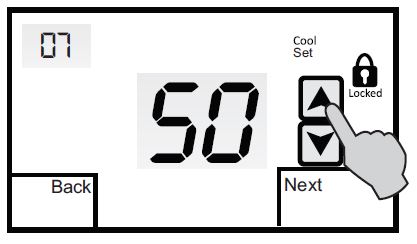
SELECTING THE COOLING SETPOINT LIMIT
Menu 07 selects the minimum cooling setpoint. The factory default is 50. Touch the UP or DOWN arrows to adjust the limit from 43° – 122°F.
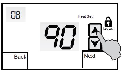
SELECTING THE HEATING SETPOINT LIMIT
Menu 08 selects the maximum heating setpoint limit. The factory default is 90. Touch the UP or DOWN arrows to adjust the limit from 41° – 120°F.
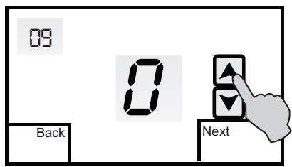
SELECTING BACKLIGHT OPTION
Menu 09 allows you to select the backlight option. The factory default is 0. Touch the UP or DOWN arrows to change the display option
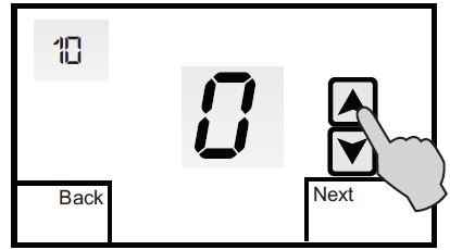
SELECTING THE ADAPTIVE RECOVERY OPTION
Menu 10 allows you to select the Adaptive Recovery option. Only displayed when 01 is set to 7. Adaptive Recovery compares the space temperature deviation from the setpoint and the rate of recovery history to bring the equipment on and reach the setpoint at the scheduled start time. The factory default is 0. Touch the UP or DOWN arrows to select this option.
SELECTING FIRST STAGE HEATING AND COOLING DIFFERENTIAL OPTION
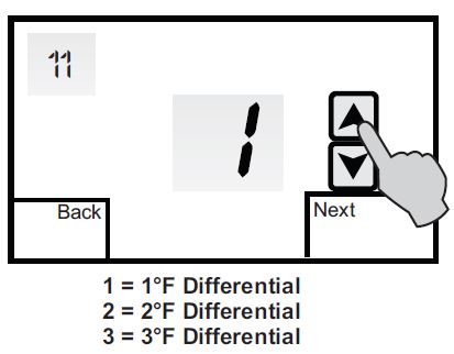
Menu 11 is used to adjust the heating and cooling differential. The factory default is (1°F). This represents the temperature above the cooling setpoint or below the heating setpoint when the equipment is energized. Touch the UP or DOWN arrows to change the differential.
SELECTING SECOND STAGE HEATING AND COOLING DIFFERENTIAL OPTION
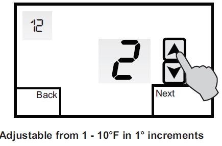
Menu 12 is used to adjust the second stage heating and cooling differential. The factory default is 2 (2°F). This represents the temperature above the first stage cooling differential or below the first stage heating differential when the second stage is energized. Touch the UP or DOWN arrows to change the differential.
SELECTING THIRD STAGE HEATING DIFFERENTIAL OPTION
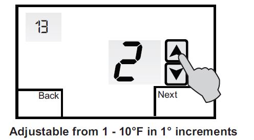
Menu 13 is used to adjust the third-stage heating differential. Only displayed when SW1 and SW 3 are ON. The factory default is 2 (2°F). This represents the temperature below the second-stage heating differential when third-stage heat is energized. Touch the UP or DOWN arrows to change the differential.
SELECTING DEMAND STAGING OR LOCKED STAGING OPTION
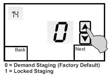
Menu 14 is used to select how the thermostat will stage the equipment. The factory default is 0 which = Demand Staging. Demand Staging allows the thermostat to upstage or downstage the equipment based on the stage differential settings. In dual fuel setup, the thermostat will not downstage to the compressor if fossil fuel is energized. 1 = Locked Staging. Locked Staging allows the thermostat to upstage the equipment based on the stage differential settings but locks in each stage until the setpoint is reached. (No downstaging)
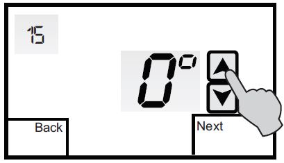
SENSOR CALIBRATION
Menu 15 allows you to re-calibrate the internal or a single indoor remote sensor. When a remote sensor is wired to the SC and S1 terminals, the internal sensor is automatically disabled. The factory default is 0 (0°F). Touch the UP or DOWN arrows to adjust the calibration from -9° to +9°F.
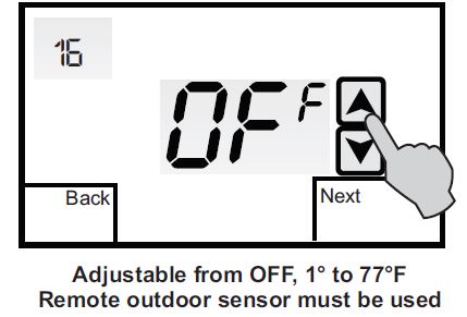
SELECTING THE LOW BALANCE POINT OPTION
Menu 16 allows you to select a low balance point setting when the thermostat is configured for Heat Pump or Dual Fuel and an outdoor sensor is used. When the outdoor temperature falls below the balance point setting, the compressor is locked out and only auxiliary electric heat or dual fuel furnace is used for heating. The factory default is OFF. Touch the UP or DOWN arrows to select a low balance point setting.
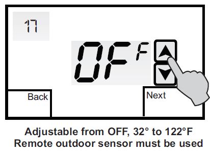
SELECTING HIGH BALANCE POINT OPTION
Menu 17 allows you to select a high balance point setting when the thermostat is configured for Heat Pump or Dual Fuel. When the outdoor temperature rises above the balance point setting, the auxiliary electric heat or dual fuel furnace is locked out and only the heat pump is used for heating. The factory default is OFF. Touch the UP or DOWN arrows to select a high balance point setting.
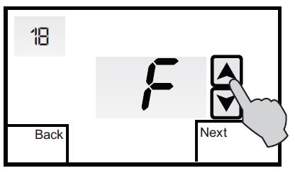
SELECTING FAHRENHEIT OR CELSIUS
Menu 18 allows you to select temperature readings and temperature setpoints in Fahrenheit or Celsius. The factory default is F (Fahrenheit). Touch the UP or DOWN arrows to select C (Celsius).
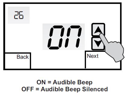
SELECTING AUDIBLE ON/OFF
Menu 26 allows you to select an audible beep whenever the screen is touched or to silence the beep. The factory default is audible beep ON. Touch the UP or DOWN arrows to change the selection.
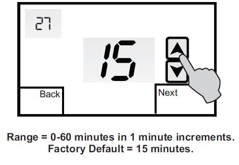
TIMED VENTILATION DURATION
Menu 27 is used to select Timed Ventilation when Menu 05 is set to 3. Timed Ventilation is used to bring outside air into the home at a controlled CFM rate based on ASHRAE 62.2 – 2013 Ventilation and Indoor Air Quality Standard. See the Ventilation Reference Chart on page 54 to calculate ventilation minutes per hour.
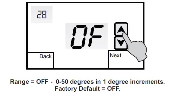
TIMED VENTILATION LOW-TEMPERATURE LIMIT
Menu 28 is used to select a low outdoor temperature when a remote outdoor sensor is installed. If the temperature is lower than or equal to the selected value, Timed Ventilation is suspended. Menu 28 is only displayed if the thermostat is fitted with an outdoor sensor
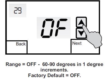
TIMED VENTILATION HIGH-TEMPERATURE LIMIT
Menu 29 is used to select a high outdoor temperature limit when a remote outdoor sensor is installed. If the temperature is higher than or equal to the selected value, Timed Ventilation is suspended. Menu 29 is only displayed if the thermostat is fitted with an outdoor sensor.
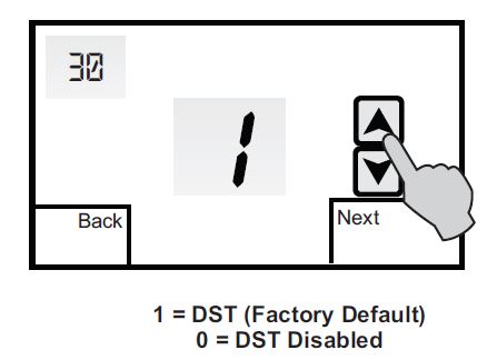
DAYLIGHT SAVING TIME
Menu 30 is used to enable or disable Daylight Saving Time (DST). In areas of the country where DST is not observed, the feature can be disabled. Touch the UP or DOWN arrows to change the selection
REMOTE SENSOR INSTALLATION
| Temperature Resistance (°F) (KΩ) | Temperature Resistance (ºF) (KΩ) | ||
| 30 | 34.6 | 70 | 11.9 |
| 40 | 26.1 | 80 | 9.4 |
| 50 | 19.9 | 90 | 7.4 |
| 60 | 15.3 | 100 | 5.9 |
REMOTE SENSOR TYPES
The thermostat can accommodate both an indoor and outdoor remote sensor. For indoor applications, the TS-1 remote sensor can be wired to the thermostat SC and S1 terminals. Each sensor contains two thermistors wired in series with a switch to select one or both sensors. This reduces the total number of sensors required for series/parallel temperature averaging. Whenever an indoor remote sensor is used, the thermostat’s internal sensor is automatically disabled. The T-OTS outdoor remote sensor is wired to the SC and S2 terminals. The outdoor sensor thermistor is housed in a waterproof encapsulation and is ideally suited for ambient conditions ranging from -40 to 140°F and humidity levels of 5 to 95% RH (non-condensing).
T-S1 INDOOR SENSOR INSTALLATION
Locate the sensor in the same manner as the thermostat. Mount the sensor 18” away from any outside wall. Do not install the sensor behind doors, in corners or other dead air spaces. Keep the sensor away from direct airflow, supply registers or near sources of heat such as lamps and appliances.
Use a separate 18-2 shielded cable for sensor wiring. Prior to wiring the sensor to the thermostat, use an ohm-meter or multi-meter to measure the resistance of the sensor. Measure at the end of the wires that will connect to the thermostat. Confirm the resistance value (within 5%) to the temperature where the sensor is mounted. Refer to the Temperature/Resistance Chart on page 41 of this manual. Use a high quality, digital electronic thermometer to read the temperature at the sensor. Remove the sensor cover and place the thermometer probe next to the thermistor to verify an accurate reading. Disconnect power to the thermostat when wiring the sensor to the proper sensor terminals. Strip only as much insulation off of the wires as necessary to provide a good contact with the terminals. The sensor is not polarity specific so either sensor lead may be connected to either designated terminal on the thermostat. Refer to the T-S1 installation guide for additional information
T-OTS OUTDOOR SENSOR INSTALLATION
When the T-OTS is wired to the UT32, it will display the outside air temperature as well as control high and low balance points for heat pump or dual fuel systems. Refer to the T-OTS installation guide for additional information.
TEMPERATURE/RESISTANCE CHART
DISPLAY FUNCTIONS

TESTING
FAN OPERATION
Touch Mode until the word OFF is displayed. Touch FAN until the words Always On appear. After a brief moment, the internal fan relay ‘G’ will energize and the system fan should operate. Touch FAN again until the word Automatic appears. After a brief moment, the internal fan relay will de-energize and the system fan will shut off.
CONVENTIONAL HEATING
Touch Mode until the word Heat appears. Touch the UP arrow and raise the setpoint above the space temperature and the first stage differential. After a brief moment, the internal heating relay ‘W1’ will energize and the heating system should operate. The word Heat will flash continuously. If the thermostat has been configured for two stage heating, raise the setpoint above the second stage differential and Heat 2 will flash indicating the ‘W2’ heating relay is energized. Touch Mode until the word OFF is displayed.
CONVENTIONAL COOLING
Touch Mode until Cool appears. Touch the DOWN arrow and lower the setpoint below the space temperature and the first stage differential.
Note: On a call for cooling, the thermostat activates a 3 minute time delay before the cooling relay ‘Y1’ is energized. Mode will flash to indicate the thermostat is in time delay. After the time delay, the internal fan ‘G’ and cooling relay ‘Y1’ will energize. The word Cool will flash. If the thermostat has been configured for two stage cooling, lower the setpoint below the second stage differential and Cool 2 will flash indicating the ‘Y2’ cooling relay is energized. Touch Mode until the word OFF is displayed.
CONVENTIONAL HEAT PUMP
When the thermostat is configured for conventional heat pump operation, testing is the same as a heating and cooling system with the exception that a 3 minute time delay is activated before the ‘Y1’ compressor relay will energize on a call for heating or cooling. Mode will flash to indicate the thermostat is in time delay. Depending on the mode of operation and equipment configuration, Heat or Cool will flash when the ‘Y1’ compressor relay is energized. Heat 2 or Cool 2 will flash when the ‘Y2’ compressor relay is energized. Heat 2 3 will flash when the auxiliary ‘W1’ relay is energized. E.Heat will flash when the mode is set to emergency heat. After testing, touch Mode until the word OFF is displayed
DUAL FUEL
When the thermostat is configured for dual fuel operation, testing is the same as a heating and cooling system with the exception that a 3 minute time delay is activated before the ‘Y1’ compressor relay will energize on a call for heating or cooling. Mode will flash to indicate the thermostat is in time delay. Depending on the mode of operation and equipment configuration, Heat or Cool will flash when the ‘Y1’ compressor relay is energized. Heat 2 or Cool 2 will flash when the ‘Y2’ compressor relay is energized. Heat 3 will flash when the auxiliary ‘W1’ relay is energized. E.Heat will flash when the mode is set to emergency heat. Whenever the thermostat calls for auxiliary heat, the heat pump compressor or compressors will be de-energized and the auxiliary heat will remain on until the call is satisfied.
LOW BALANCE POINT (Heat Pump or Dual Fuel)
When an outdoor sensor is used with the thermostat, Installer Option 16 allows you to select a low balance point temperature. When the outdoor temperature falls below the low balance point setting, a call for heat from the thermostat automatically energizes the ‘W1’ relay and bypasses the ‘Y1’ compressor relay.
TESTING
To test the low balance point setting, set Option 16 above the displayed outdoor temperature and force a call for heating. Only the auxiliary heat relay ‘W1’ should energize. After testing, reset the low balance point setting to a normal operating range.
HIGH BALANCE POINT (Heat Pump or Dual Fuel)
High balance point is designed to prevent the auxiliary heat ‘W1’ relay from energizing when the outdoor temperature is above the balance point setting. To test the high balance point setting, set Option 17 below the displayed outdoor temperature and force a call for auxiliary heat. Only the compressor ‘Y1’ and/or ‘Y1’ and ‘Y2’ should energize. If the thermostat is placed in the E.Heat (emergency heat) mode, the ‘W1’ relay will energize. After testing, reset the high balance point setting to a normal operating range.
ADAPTIVE RECOVERY
Adaptive Recovery is only available in programmable mode (Installer Option 01 = 7) The Adaptive Recovery function of the thermostat permits the user to program a time that a desired set temperature is required. The thermostat then calculates the most energy-efficient time to bring on the equipment to reach the setpoint at
PROGRAMMABLE FAN
A programmable Fan (Installer Option 04 = 0) is used to program the fan operation along with the thermostat schedule. This is a very convenient feature that allows selecting continuous (Always ON) or Automatic fan operation for each scheduled event. When Programmable Fan is used, the fan operation can still be overridden at the thermostat and will remain in the override mode until the next scheduled event.
AUXILIARY CONTACTS
The Auxiliary Contacts (Installer Option 05) provide a selectable normally open (1) or normally closed (2) dry contact output that works in conjunction with the Programmable Fan feature when the thermostat is configured for programmable mode. When the fan is in continuous (Always ON) mode, the auxiliary relay coil is energized and de-energizes in Automatic mode. The Auxiliary Contacts may also be used for Timed Ventilation when Installer Option 05 is set to 3.
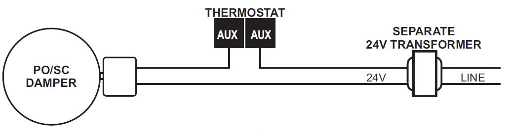
The auxiliary dry contacts can be used with the Programmable Fan feature when the Programmable Fan Option 04 is ON. They can also be used for Timed Ventilation when Option 05 is set to 3. Timed Ventilation is designed to improve residential indoor air quality by introducing fresh, outside air through a 2-wire, power open / spring closed motorized intake damper controlled by the thermostat. The thermostat controls the amount of fresh air required each hour based on ASHRAE 62.2 – 2013 Ventilation and Indoor Air Quality Standard. The reference chart on the next page provides the ventilation timer setting based on using an 8” outside air damper ducted to the return air plenum on the HVAC system. A separate 24 volt transformer should be used to power the damper
TIMED VENTILATION SETUP
The reference chart below provides the ventilation timer setting (Installer Option 27) based on using 8” rigid straight duct with friction loss of 0.1” w.g. per 100 ft. This chart can be used for most applications.
| VENTILATION TIMER SETTING (MINUTES PER HOUR) | ||||||
| NUMBER OF BEDROOMS | ONE | TWO | THREE | FOUR | FIVE | |
|
HOME SIZE (Ft²) |
<500 | 8 | 10 | 12 | 15 | 16 |
| 501-1000 | 12 | 15 | 16 | 19 | 21 | |
| 1001-1500 | 16 | 19 | 21 | 23 | 25 | |
| 1501-2000 | 21 | 23 | 25 | 27 | 29 | |
| 2001-2500 | 25 | 27 | 29 | 31 | 33 | |
| 2501-3000 | 29 | 31 | 33 | 35 | 37 | |
| 3001-3500 | 33 | 35 | 37 | 39 | 41 | |
| 3501-4000 | 37 | 39 | 41 | 43 | 45 | |
| 4001-4500 | 41 | 43 | 45 | 47 | 49 | |
| 4501-5000 | 45 | 47 | 49 | 51 | 53 | |
TROUBLESHOOTING
| SYMPTOM | POSSIBLE FAULT AND REMEDY |
| No LCD display | If the thermostat is battery powered only, remove the battery compartment and check to see that the positive (+) and negative (-) ends of each battery are oriented properly. Also make sure that the thermostat is securely attached to the subbase with no exposed gaps. |
| Thermostat can not
be set for auto changeover |
Installer Option 03 needs to be set to 0 to provide Heat/Auto/Cool/Off operation or Heat/Auto/Cool/Emergency Heat/Off for heat pumps.
03 = 1 Manual Changeover (Heat/Cool/Off) 03 = 2 Heat Only (Heat/Off) 03 = 3 Cool Only (Cool/Off) |
| Temperature display inaccurate | Air from wall cavity may be leaking into the rear of the thermostat. Seal hole where wiring enters subbase to prevent air infiltration. External influence from appliances, lighting or drafts may be affecting temperature accuracy. Move lamps or other sources of heat away from thermostat. |
| Thermostat not displaying outdoor temperature | Check wiring at outdoor sensor and sensor terminals on subbase. Outdoor sensor wires to terminals S2 and SC. |
| SYMPTOM | POSSIBLE FAULT AND REMEDY |
| Heat or Cool is flashing | This is not a fault but indicates that the thermostat heating or cooling relay is energized. Depending upon the equipment configuration, Heat 2 or Cool 2 will also be displayed if a second stage is energized. Heat 3 is also displayed for heat pumps having three heating stages. |
| Lock icon is displayed when trying to set a higher or lower temperature | This is not a fault. The thermostat heating and cooling limits are preventing setting a temperature above or below the limit values. These values can be changes in the Installer Menu.
07 = Cooling Limit. Factory default is 50° F. Adjustable from 43° F to 122° F. 08 = Heating Limit. Factory default is 90° F. Adjustable from 41° F to 120° F. |
|
The fan continues to run after a heating or cooling call is satisfied |
The thermostat fan mode may be set to Always On. Touch the fan icon and change it to Automatic. When the thermostat is configured as a programmable thermostat, the fan operation can be programmed for Automatic or Always On with each event. If the Programmable Fan feature is not required, set Option 04 = 1. |
| Some functions cannot be changed and a padlock | Lock values have been set. Refer to Installer Option menu 06. To remove all lock values, set 06 = 0. |
SPECIFICATIONS
- Input Voltage (Hardwired) 20-30 VAC 50/60 Hz
- Relay Rating 24 VAC @ 1 Amp maximum per relay
- Battery Power (2) AA 1.5 V
- Operating Temperature 32° F to 150° F
- Operating Relative Humidity 0-95% RH (non-condensing)
- Storage Temperature 32° F to 150° F
- Overall Size 5.5” W x 3.75” H x 1.312” D
- LCD Display Size 4.125” W x 2.375” H
- Back Light Blue LED
- Short-cycle Delay 4 minutes
- Displayed Temperature Resolution 1° F
- Setpoint Range
- Heating 41° F – 120° F
- Cooling 43° F – 122° F
- Heating and Cooling Limits Fully adjustable
- Onboard and Remote Sensors NTC type 2
- Resistance 10KΩ @ 77° F
- Tolerance + / – 3% @ 77° F
- Warranty 5 years
Reference
Download Manual:
Io-HVAC-controls UT32 Programmable Touchscreen Thermostat Installation Manual
Other Manual:
Io-hvac-controls UT32 Programmable Touchscreen Thermostat User Manuals
![]()
Io-HVAC-controls UT32 Programmable Touchscreen Thermostat Installation Manual
Leave a Reply