Mco-home A8-9 Electrical Heating Thermostat
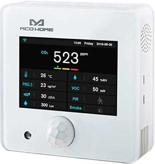
MCOHome A8-9 is a Z-Wave enabled multiple environmental monitoring sensors, with 3.5 inch TFT clear display and compliant to Z-Wave Plus standard. It is built in with Temperature, Humidity, PM2.5, CO2, VOC, PIR, illumination, Noise, Smoke sensors. Device can be added into any Z-Wave network, and is compatible with any other Z-Wave certified devices.
Technical Data
- Temperature: 0~50℃
- Humidity: 0%RH~99%RH
- PM2.5: 0~500ug/m3
- CO2: 0~5000ppm
- VOC: 0-64000ppb
- PIR: 0 or 1 Detection angle up to 120°
- Illumination: 0~40000Lux
- Noise: 30dB~100dB
- Smoke: 0 or 1
Specification
- Power Supply: DC12V
- Self-dissipation:<3W
- Work environment:-20~+60℃ <99%RH (Non-condensation)
- Dimension: 110* 110*32mm
- Hole Pitch: 60mm or 82mm
- Housing: Tempered glass+ PC Alloy
- Installation: Wall-mounted (Vertical)
Safety Information
To protect yourself and others from danger and to protect the device from damage, please read the safety information before using it.
Important
- A qualified electrician with the understanding of wiring diagrams and knowledge of electrical safety should complete installation following the instructions.
- Before installation, please confirm the real voltage complying with the device’s specification.
- Cut off any power supply to secure the safety of people and device.
- During installation, protect the device from any physical damage by dropping or bumping. If happens, please contact the supplier for maintenance.
- Keep the device away from acid-base and other corrosive solids, liquids, gases, to avoid damage.
- Avoid overexertion during operation, to protect device from mechanical damage.
- Read all instructions and documentation and save for future reference.
Installation &Wiring
Location
Device is suggested to be installed indoor, a place with around 1.5m height above the floor where represents the average CO2 concentration. It should be away from direct sunlight, any cover, or any heat source, to avoid false signal for temperature control.
Notice
- Device must be wall-mounted vertically. Do not lay it flat or upside down while working.
- Do not mounted it in a wind gap, or cover its bottom, which may affect the detected data.
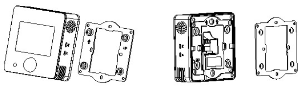
- Step 1: Remove the steel frame from the backside of the device, and then fix it onto the installation box with 2 screws.
- Step 2: Wire the adaptor.
- Step 3: Put the device back onto the steel frame, it will attach with the frame firmly by built-in magnets.
- Step 4: Check the installation and power, the device is ready for work.
Operation
Power on/ power off
- Wire the adaptor and the device is powered on. It will display all detected information by the sensors.
Display interface
Hold Key F1 can switch among the following 4 display interfaces:
- Data detecting: display all sensors’ data
- Network: Z-Wave Add/Remove
- Data calibration: to calibrate the detected data manually
- Local time setting
Z-Wave Operation
Note: A Security Enabled Z-Wave Controller must be used in order to fully utilize the product.
Add &Remove Z-Wave network
- Activate Add/Remove mode in the gateway. When device is powered on, hold F1 to choose interface for Add or Remove Z-Wave network.
- Click F2 five times until
 turns blue.
 - Hold F2 and the device enters into learning mode, then
 turns blue and the device is added into Z-Wave network.
 - Follow the same steps to remove the device from network.
Association Group
Device supports 1 association group:
| AG
identifier |
Max
Node ID |
Command Classes | Trigger situation |
| 0x01 | 1 | COMMAND_CLASS
_SENSOR_MULTIL EVEL_V5, SENSOR_MULTILE VEL_REPORT_V5 |
Detected value will be reported according to:
|
Command Class supported by the device: ( Supports S2 unauthenticated level)
- COMMAND_CLASS_VERSION,
- COMMAND_CLASS_MANUFACTURER_SPECIFIC,
- COMMAND_CLASS_DEVICE_RESET_LOCALLY,
- COMMAND_CLASS_POWERLEVEL,
- COMMAND_CLASS_ASSOCIATION,
- COMMAND_CLASS_ASSOCIATION_GRP_INFO,
- COMMAND_CLASS_CONFIGURATION,
- COMMAND_CLASS_SENSOR_MULTILEVEL,
- COMMAND_CLASS_FIRMWARE_UPDATE_MD
Command Class supported by the device: (Not supports S2)
- COMMAND_CLASS_ZWAVEPLUS_INFO,
- COMMAND_CLASS_TRANSPORT_SERVICE_V2,
- COMMAND_CLASS_SECURITY_2,
- COMMAND_CLASS_SUPERVISION
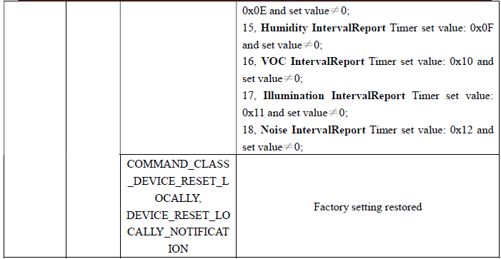
Restore Factory Setting
- Press & hold F1 to enter Z-Wave setting interface, then press & hold F1 again to enter parameters setting interface;
- Press & hold F2 to enter setting interface and select “default”;
- Click F2 3 times and displays “OFF”–>“ON”–>“OK”–>“OFF”, factory setting is restored.
Note: Please use this procedure only when the network primary controller is missing or otherwise inoperable.
Data Calibration
- Hold F1 to choose interface for data calibration. Then hold F2 to switch among the sensors. Choose one and click F2, F1 to change the data. After finished, hold F1 can return data detecting interface.
Local time setting
- Hold F1 to choose interface for local time setting. Then hold F2 to switch among “Hour-Minute-Second-Year-Month-Date”. Click F2, F1 can change the data of flashing item.
- After finished, hold F1 can return data detecting interface.
Parameters table
| Add | Parameter | Byte | Options | Default | Range |
|
0x01 |
PM25_Delta_Level |
1 |
=0 Turn off report
>=1 Report when change > n * 1ug/m3 |
0 |
0-127 |
|
0x02 |
CO2_Delta_Level |
1 |
=0 Turn off report
>=1 Report when change > n * 5ppm |
0 |
0-127 |
|
0x03 |
Temp_Delta_Level |
1 |
=0 Turn off report
>=1 Report when change > n*0.5℃ |
0 |
0-127 |
| 0x04 | Humidity_Delta_Level | 1 | =0 Turn off report
>=1 Report when change >n% |
0 | 0-127 |
|
0x05 |
VOC_Delta_Level |
1 |
=0 Turn off report
>=1-127*5ppb Reportchange |
0 |
0-127 |
|
0x06 |
Lux_Delta_Level |
2 |
=0 Turn off report
>=1 Report when change > n*1 Lux |
0 |
0-32767 |
|
0x07 |
dB_Delta_Level |
1 |
=0 Turn off report
>=1 Report when change > n*1dB |
0 |
0-127 |
|
0x08 |
PIR_Delta_Level |
1 |
=0 Turn off report
=1 Report change |
0 |
0-1 |
| 0x09 | SMOKE_Delta_Level | 1 | =0 Turn off report
=1 Report change |
1 | 0-1 |
|
0x0A |
Smoke_Timer |
2 |
=0 Turn off report
>=35 Report every n*1s interval |
60 |
0,35-32767 |
|
0x0B |
PIR_Timer |
2 |
=0 Turn off report
>=35 Report every n*1s interval |
60 |
0,35-32767 |
|
0x0C |
PM25_Timer |
2 |
=0 Turn off report
>=35Report every n*1s interval |
120 |
0,35-32767 |
| 0x0D | CO2_Timer | 2 | =0 Turn off report | 120 | 0,35-32767 |
| >=35 Report every n*1s
interval |
|||||
|
0x0E |
Temp_Timer |
2 |
=0 Turn off report
>=35 Report every n*1s interval |
180 |
0,35-32767 |
|
0x0F |
Humidity_Timer |
2 |
=0 Turn off report
>=35 Report every n*1s interval |
180 |
0,35-32767 |
|
0x10 |
VOC_Timer |
2 |
=0 Turn off report
>=35 Report every n*1s interval |
180 |
0,35-32767 |
|
0x11 |
Lux_Timer |
2 |
=0 Turn off report
>=35 Report every n*1s interval |
300 |
0,35-32767 |
|
0x12 |
dB_Timer |
2 |
=0 Turn off report
>=35 Report every n*1s interval |
300 |
0,35-32767 |
| 0x2F | Temp. unit | 1 | =0 ℃
=1 ℉ |
0 | 0-1 |
|
0x32 |
T_OffSet |
1 |
0 ~ 127:
((n-100)/10)=(-10~2.7)℃ -128 ~ -1: ((156+n)/10)=(2.8~15.5)℃ |
100 |
-128-127 |
|
0x33 |
RH_OffSet |
1 |
n-20=(-20~20)% |
20 |
0~40 |
| 0x34 | CO2_OffSet | 2 | (n-500)=(-500~500)ppm | 500 | 0~1000 |
|
0x35 |
PM2.5_OffSet |
1 |
0 ~ 127:
n-100=(-100~27)ug/m3 -128 ~ -1: 156+n=(28~155)ug/m3 |
100 |
-128-127 |
| 0x36 | Lux_OffSet | 2 | n-5000=(-5000~5000)lux | 5000 | 0~10000 |
|
0x37 |
VOC_Correct |
1 |
0 ~ 127:
n-100=(-100~27)ppb -128 ~ -1: 156+n=(28~155)ppb |
100 |
-128-127 |
| 0x38 | dB_Correct | 1 | (n-50)=-50~50 | 50 | 0~100 |
| 0xFF | Write Only | 1 | ==0x55 Restore factory setting
==0xAA Restore default para. |
Warranty
1-year Limited Warranty
MCOHome warrants this product to be free from defects in material and workmanship under normal and proper use for one year from purchase date of the original purchaser. MCOHome will, at its option, either repair or replace any part of its products that prove defective by reason of improper workmanship or materials.THIS LIMITED WARRANTY DOES NOT COVER ANY DAMAGE TO THIS PRODUCT THAT RESULTS FROM IMPROPER INSTALLATION, ACCIDENT, ABUSE, MISUSE, NATURAL DISASTER, INSUFFICIENT OR EXCESSIVE ELECTRICAL SUPPLY, ABNORMAL MECHANICAL OR ENVIRONMENTAL CONDITIONS, OR ANY UNAUTHORIZED DISASSEMBLY, REPAIR OR MODIFICATION.
This limited warranty shall not apply if:
- the product was not used in accordance with any accompanying instructions.
- the product was not used for its intended function. This limited warranty also does not apply to any product on which the original identification information has been altered, obliterated or removed, that has not been handled or packaged correctly, that has been sold as second-hand or that has been resold contrary to Country and other applicable export regulations.
Reference
Download Manual:
Mco-home A8-9 Electrical Heating Thermostat Instruction MANUAL
Mco-home A8-9 Electrical Heating Thermostat Instruction MANUAL