
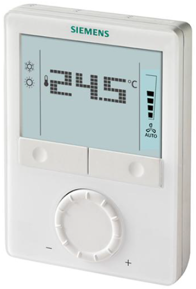
SIEMENS RDG100 Room Thermostat
Wall-mounted room thermostats with LCD
- for fan coil unit applications
- for universal applications
- for use with compressors in DX-type equipment
- RDG100..: Operating voltage AC 230 V, On/Off, 3-positon or PWM control outputs
- RDG110: Operating voltage AC 230 V, On/Off relay (SPDT) outputs
- RDG110U: Operating voltage AC/DC 24 V, On/Off relay (SPDT) outputs
- RDG100../RDG110..: Output for 1-speed and 3-speed
- RDG160T..: Operating voltage AC/DC 24 V, DC 0…10 V or On/Off control outputs
- RDG160T..: Output for 1-speed, 3-speed or ECM fan DC 0…10 V
- Operating modes: Comfort, Economy and Protection
- Automatic or manual fan speed
- 3 multifunctional inputs for keycard contact, external sensor, etc
- Automatic or manual heating/cooling changeover
- Adjustable commissioning and control parameters
- Minimum and maximum setpoint limitation
- Backlit display
- Additional features of RDG100T, RDG160T..:
- The infrared remote control receiver
- Auto Timer mode with 8 programmable timers
- The auto timer can be disabled via P02
- Auto timer can be disabled via DIP switches (RDG160T..)
- Selectable relay output functions (RDG160T..)
- Power reserve clock for 48 h during power failure
Use
The RDG1.. room thermostats are designed for use with the following types of system:
Fan coil units via On/Off or modulating control outputs:
- 2-pipe system
- A 2-pipe system with electric heater
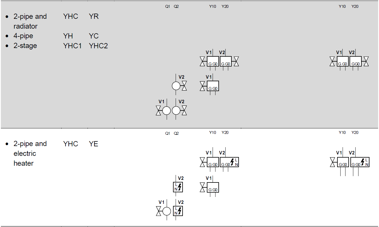
- 2-pipe system and radiator/floor heating
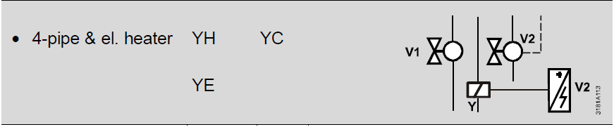
- 4-pipe system
- A 4-pipe system with electric heater
- 2-stage heating or cooling system
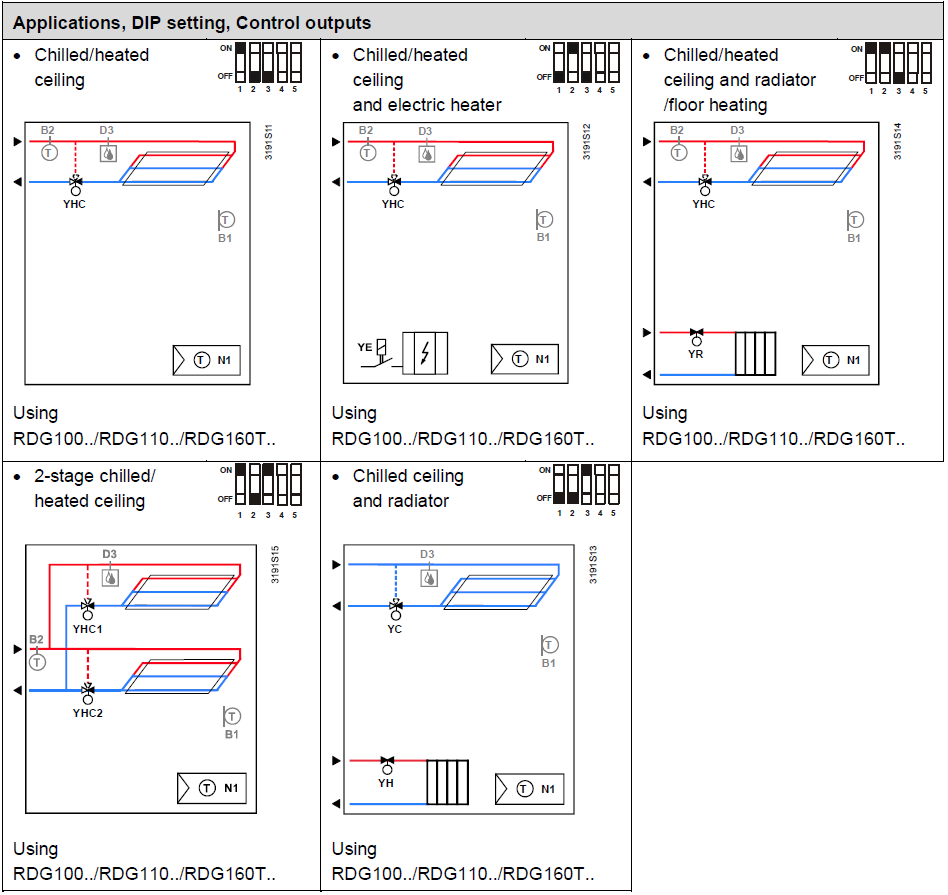
Chilled/heated ceilings (or radiators) via On/Off or modulating control outputs:
- Chilled/heated ceiling
- Chilled/heated ceiling with electric heater
- Chilled/heated ceiling and radiator/floor heating
- Chilled/heated ceiling, 2-stage cooling or heating
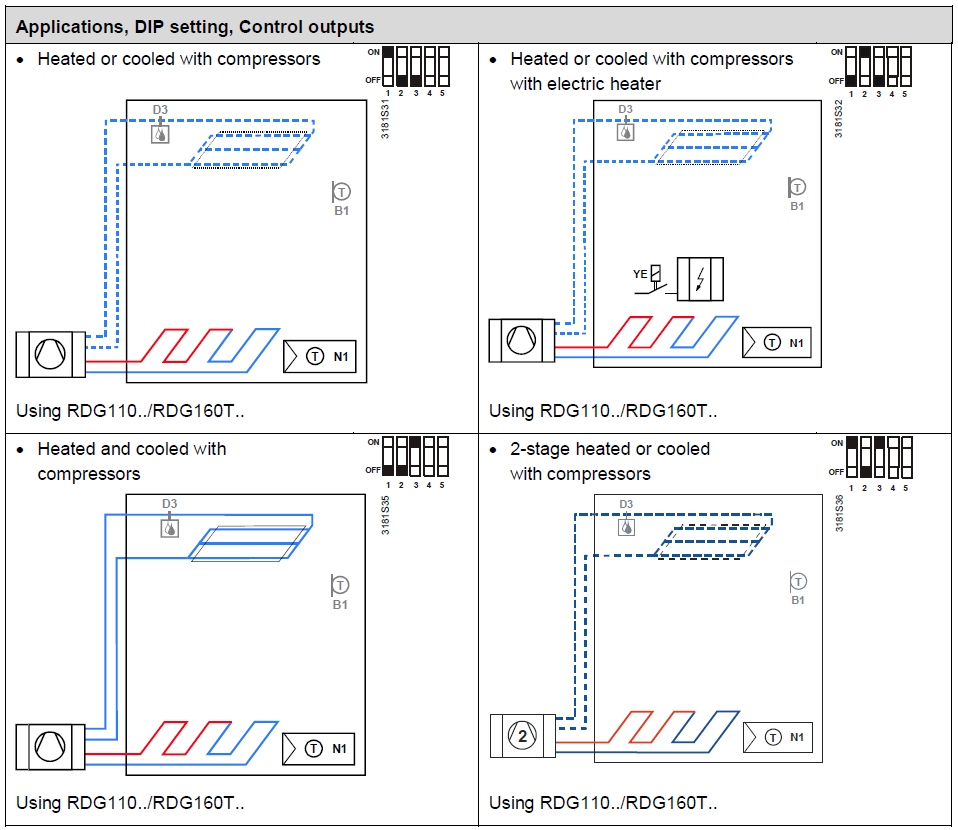
Heat pumps with dx-type equipment:
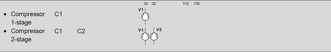
- 1-stage compressor for heating or cooling
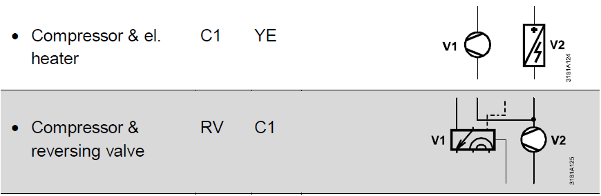
- 1-stage compressor for heating or cooling with electric heater
- 1-stage compressor for heating or cooling and radiator/floor heating
- 1-stage compressor for heating and cooling
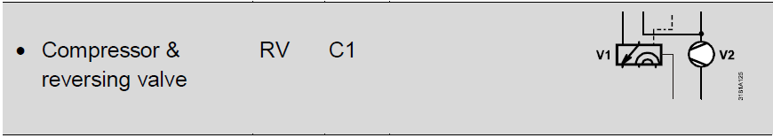
- 1-stage compressor for heating and cooling with reversing valve
- 2-stage compressor for heating or cooling
Functions
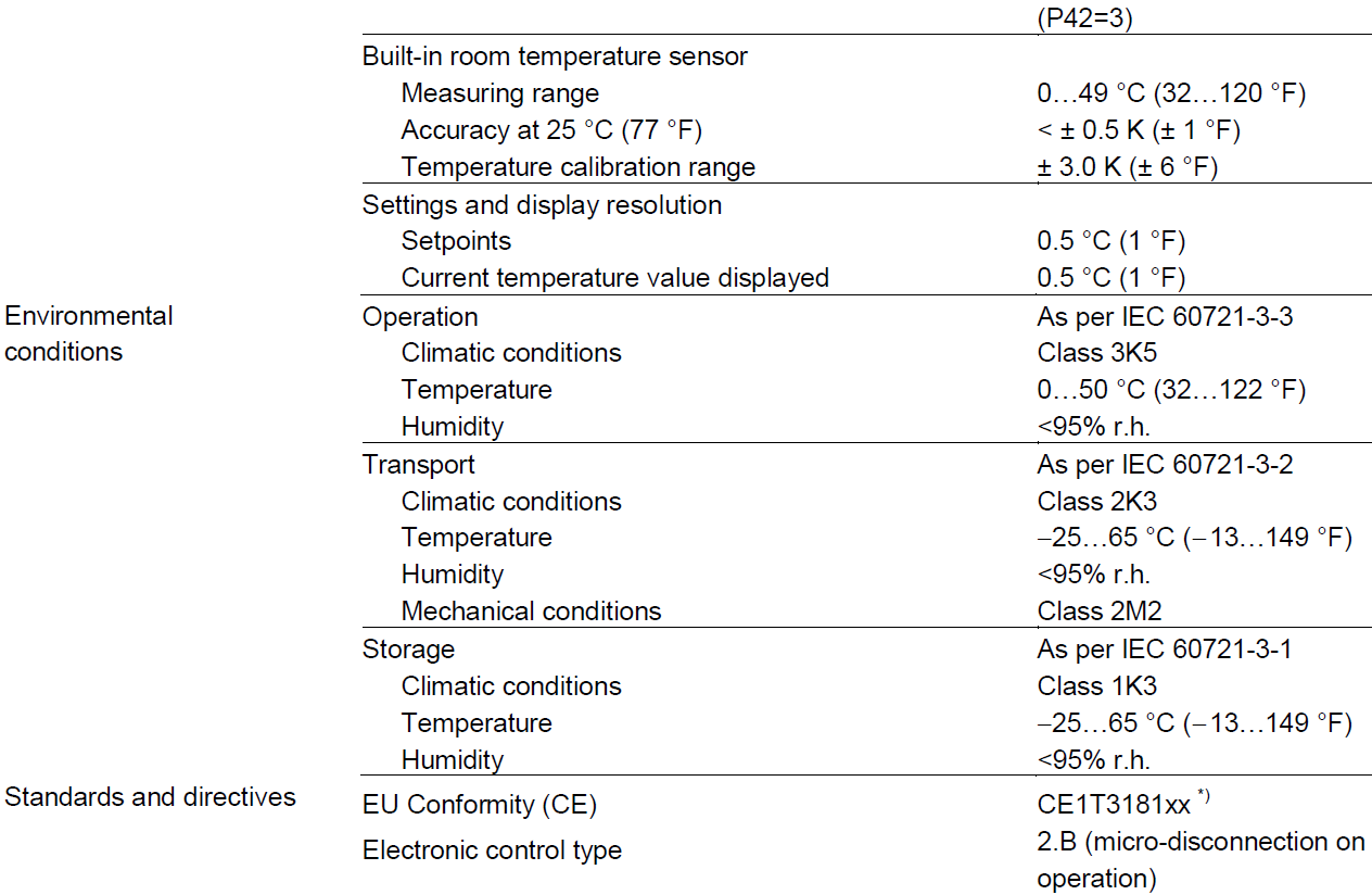
- Maintenance of room temperature via built-in temperature sensor or external room temperature/return air temperature sensor
- Automatic or manual changeover between heating and cooling mode
- Selection of applications via DIP switches
- Selection of operating mode via the operating mode button on the thermostat
- 1-speed, 3-speed or DC 0…10 V fan control (automatic or manual)
- Display of current room temperature or setpoint in °C and/or °F
- Minimum and maximum setpoint limitation
- Button lock (automatic or manual)
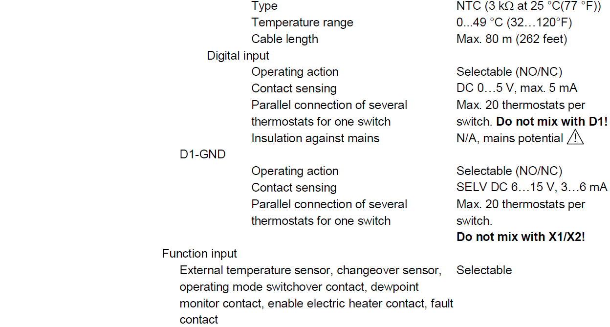
- 1 digital input, freely selectable for:
- Operating mode switchover contact (keycard)
- Automatic heating/cooling changeover contact
- Electric heater enable
- Dewpoint sensor
- Fault input
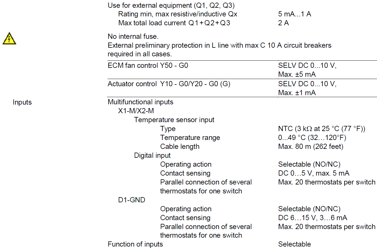
- 2 multifunctional inputs, freely selectable for:
- Operating mode switchover contact (keycard)
- Automatic heating/cooling changeover sensor
- External room temperature or return air temperature
- Dewpoint sensor
- Electric heater enable
- Fault input
- Supply air temperature sensor (RDG160T..)
- Advanced fan control function, i.e. fan kick, fan start, selectable fan operation
(enable, disable or depending on heating or cooling mode) - Purge function together with 2-port valve in a 2-pipe changeover system
- Reminder to clean filters
- Floor heating temperature limit
- Minimum and maximum supply air temperature limitation (RDG160T..)
- Reloading factory settings for commissioning and control parameters
- 7-day time program: 8 programmable timers to switch over between Comfort and Economy mode (RDG100T, RDG160T..)
- Infrared remote control (RDG100T, RDG160T..)
- Selectable relay function (RDG160T..)
- For switching OFF external equipment OFF during Protection mode
- For switching ON external equipment (such as. pump) during H/C demand
- Output heating/cooling sequence
- Wizard function to select working temperature unit °C or °F (RDG160TU, RDG110U)
- Power reserve clock for 48 h during power failure on RDG1..T
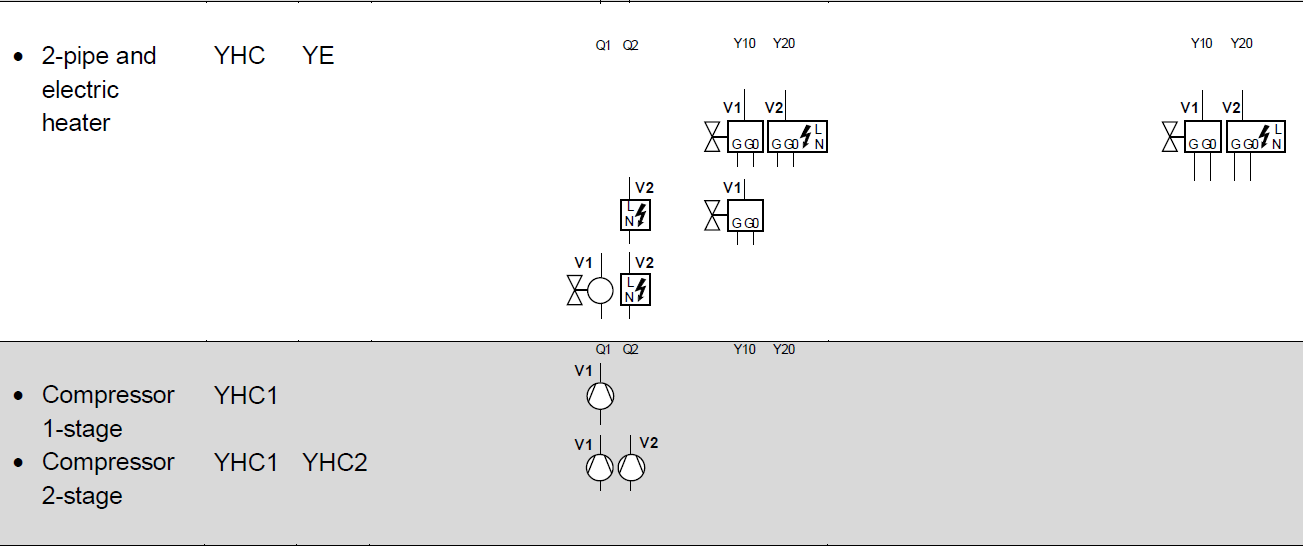
Applications
The room thermostats support the following applications, which can be configured via DIP switches at the rear of the unit. Depending on the thermostat type, On/Off or modulating control outputs are available.
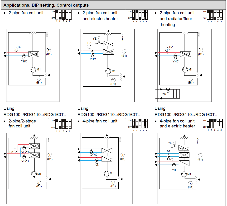
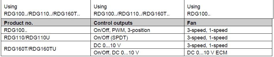
| Product no. | Control outputs |
| RDG100.. | On/Off, PWM, 3-position |
| RDG110/RDG110U | On/Off (SPDT) |
| RDG160T/RDG160TU | On/Off, DC 0…10 V |
| Product no. | Control outputs | Fan |
| RDG110/RDG110U | On/Off (SPDT) | Disabled, 3-speed, 1-speed |
| RDG160T/RDG160TU | On/Off, DC 0…10 V | Disabled, 3-speed, 1-speed, DC 0…10 V |
Legend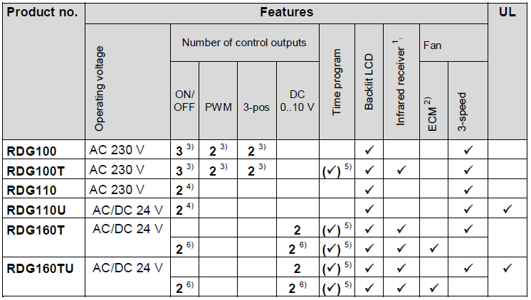
- YHC.. Heating/cooling valve actuator M1 1-speed or 3-speed fan
- YH Heating valve actuator
- YC Cooling valve actuator
- B1 Return air temperature sensor or external room temperature sensor (optional)
- YE Electric heater B2 Changeover sensor (optional)
Type summary
- Infrared remote control must be ordered as a separate item
- ECM fan output DC 0…10 V
- On/Off, PWM or 3-position (triac outputs)
- Relay output (SPDT)
- Can be disabled via P02 (or via DIP switches on RDG160T..)
- On/Off (relay output) or DC control signal
Equipment combinations
| Description | Product no. | Data Sheet |
| Infrared remote control |
IRA211 |
3059 |
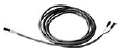
| Cable temperature sensor or changeover sensor, cable length 2.5 m (8 feet)
NTC (3 kO at 25 °C (77 °F)) |
QAH11.1 |
1840 |
Room temperature sensor NTC (3 kO at 25 °C (77 °F)) |
QAA32 | 1747 |
Cable temperature sensor, cable length 4 m (13 feet) NTC (3 kO at 25 °C (77 °F))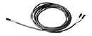 |
QAP1030/UFH |
1854 |
Condensation monitor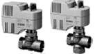 |
QXA2601/ QXA2602/ QXA2603/
QXA2604 |
3302 |
| On/Off actuators Electromotor On/Off valve and actuator(only available in AP, UAE, SA and IN) 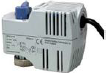 |
MVI../MXI.. | A6V11251892 |
Electromotor On/Off actuator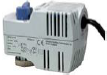 |
SFA21.. | 4863 |
Electromotor On/Off actuator |
SFP21.. | 4863 |
Zone valve actuators (only available in AP, UAE, SA and IN) |
SUA.. | 4830 |
| On/Off and PWM actuators ) Thermal actuator (for radiator valves) AC 230 V, NO  |
STA23.. |
4884 |
| Thermal actuator (for radiator valves) AC 24 V, NO |
STA73.. *) | 4884 *) |
| Thermal actuator AC 230 V (for small valves 2.5 mm (0.1″)), NC |
STP23..*) | 4884 |
Thermal actuator AC 24 V (for small valves 2.5 mm (0.1″)) NC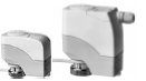 |
STP73.. *) | 4884 *) |
| 3-position actuators Electrical actuator, 3-position (for radiator valves)  |
SSA31.. | 4893 |
Electrical actuator, 3-position (for 2- and 3-port valves/V..P45) |
SSC31.. | 4895 |
| Electrical actuator, 3-position
(for small valves 2.5 mm (0.1″)) |
SSP31.. | 4864 |
Electrical actuator, 3-position (for small valves 5.5 mm (0.2″))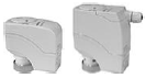 |
SSB31.. | 4891 |
| Electrical actuator, 3-position (for CombiValves VPI45) | SSD31.. | 4861 |
Electromotor actuator, 3-position (for valves 5.5 mm) |
SAS31.. | 4581 |
| DC 0…10 V actuators Electrical actuator, DC 0…10 V (for radiator valves) 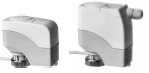 |
SSA61.. | 4893 |
| Electrical actuator, DC 0…10 V (for 2- and 3-port valves/V..P45) |
SSC61.. | 4895 |
| Electrical actuator, DC 0…10 V (for small valves 2.5 mm (0.1″)) |
SSP61.. | 4864 |
| Electrical actuator, DC 0…10 V (for small valves 5.5 mm (0.2″)) |
SSB61.. | 4891 |
| Electrical actuator, DC 0…10 V
(for CombiValves VPI45) |
SSD61.. | 4861 |
Electromotor actuator, DC 0…10 V (for valves 5.5 mm) |
SAS61.. | 4581 |
Electrothermal actuator, AC 24 V, NC, DC 0…10 V, 2 m (6.6feet) (for radiator valves and small valves 2.5 mm (0.1″)) |
STA63 |
4884 |
| Electrothermal actuator, AC 24 V, NO, DC 0…10 V, 2 m (6.6 feet) (for radiator valves and small valves 2.5 mm (0.1″)) |
STP63 |
4884 |

With PWM control, it is not possible to ensure exact parallel running of 2 or more thermal actuators. If several fan coil systems are controlled by the same room thermostat, preference should be given to motorized actuators with On/Off or 3-position control.
Note:
For more information about parallel operation and the maximum number of actuators that can be used, refer to the Data Sheets of the selected type of actuator and the following list:
- Maximum number of actuators in parallel on the RDG100..:
-
- 6 SS..31.. actuators (3-pos)
- 4 ST..23.. if used with On/Off control signal
- 10 SFA.., SUA.., MVI.., MXI.. On/Off actuators
- Parallel operation of SAS31.. is not available
- Maximum number of actuators in parallel on the RDG110..:
- 10 On/Off actuators
- Maximum number of actuators in parallel on the RDG160T..:
- 10 SS..61.. actuators (DC)
- 10 ST..23/63/73.. actuators (DC or On/Off)
- 10 SFA.., SUA.., MVI.., MXI.. On/Off actuators
- 10 SAS61.. actuators (DC)
Accessories
| Description | Product no. | Data Sheet |
| Changeover mounting kit (50 pcs/package) | ARG86.3 | 3009 |
Ordering
| Product no. | Stock no. | Designation |
| RDG100 | S55770-T158 | Room thermostat |
| RDG100T | S55770-T159 | Room thermostat, with timer |
| RDG110 | S55770-T160 | Room thermostat with relay outputs (AC 230 V) |
| RDG110U | S55770-T361 | Room thermostat with relay outputs (AC 24 V), UL certified |
| RDG160T | S55770-T343 | Room thermostat with timer and DC (or On/Off) output for valve and fan (AC 24 V) |
| RDG160TU | S55770-T362 | Room thermostat with timer and DC (or On/Off) output for valve and fan (AC 24 V), UL certified |
- Order the IRA211 infrared remote control separately.
- Order valve actuators separately.
- Order RDG110U and RDG160TU from Siemens Building Technologies USA.
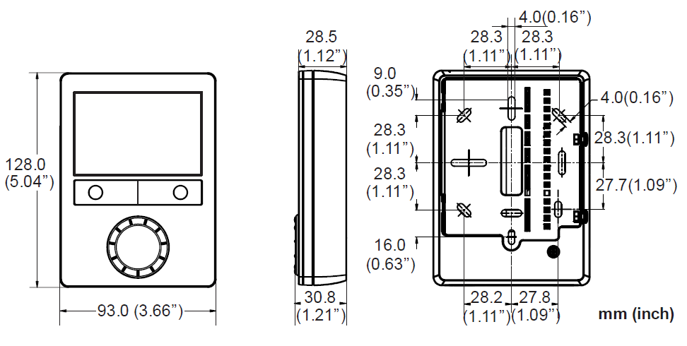
Mechanical design
The room thermostat consists of two parts:
- Plastic housing which accommodates the electronics, the operating elements and the room temperature sensor
- Mounting plate with the screw terminals
The housing engages in the mounting plate and is secured with 2 screws.
Operation and settings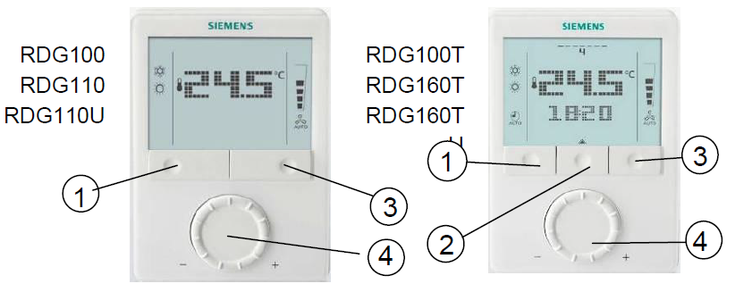
- Operating mode selector/Esc
- Button to enter the time and to set the timers
- Fan mode selector/OK
- Rotary knob for setpoint and parameter adjustment
Display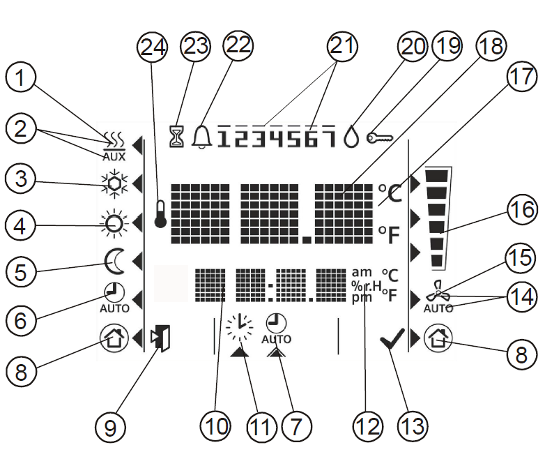
| # | Symbol | Description | # | Symbol | Description | ||
|
1 |
|
Heating mode |
14 |
|
Automatic fan |
||
|
2 |
|
Heating mode
auxiliary heater on (2nd stage) |
15 |
|
Manual fan |
||
|
3 |
|
Cooling mode |
16 |
|
Fan speed |
|
Fan speed 1 |
|
4 |
|
Comfort mode |
|
Fan speed 2 |
|||
|
5 |
|
Economy mode |
|
Fan speed 3 |
|||
|
6 |
|
Auto Timer mode |
17 |
|
Degrees Celsius Degrees Fahrenheit |
||
| 7 | View and set Auto Timer program | ||||||
|
8 |
|
Protection |
18 |
|
Digits for room temperature and setpoint display | ||
|
9 |
|
Escape |
19 |
|
Button lock |
||
|
10 |
|
Digits for time, room temperature, setpoint, etc. |
20 |
 |
Condensation in room (dewpoint sensor active) | ||
|
11 |
|
Setting the time of day and the weekday |
21 |
|
Weekday 1…7: 1 = Monday/7 = Sunday |
||
|
12 |
|
Morning: 12-hour format Afternoon: 12-hour format |
22 | |
Fault | ||
|
23 |
|
Temporary timer function (visible when
operating mode is temporarily extended due to prolonged presence or absence) |
|||||
|
13 |
|
Confirmation of parameters |
24 |
|
Indicates that room temperature is displayed |
||
Mounting and installation
Do not mount on a wall in niches or bookshelves, behind curtains, above or near heat sources, or exposed to direct solar radiation. Mount about 1.5 m (5 feet) above the floor.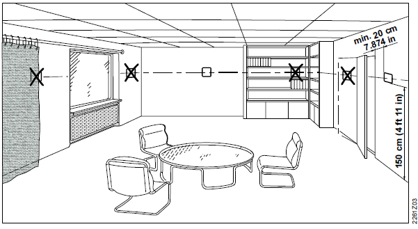
Mounting
- The room thermostat must be mounted in a clean, dry indoor place and must not be exposed to drip or splash water.
Wiring: See Mounting Instructions (M3181, M3183, M3183.1 or M3183.2) enclosed with the thermostat.
- Comply with local regulations to wire, protect and earth the thermostat.
Warning
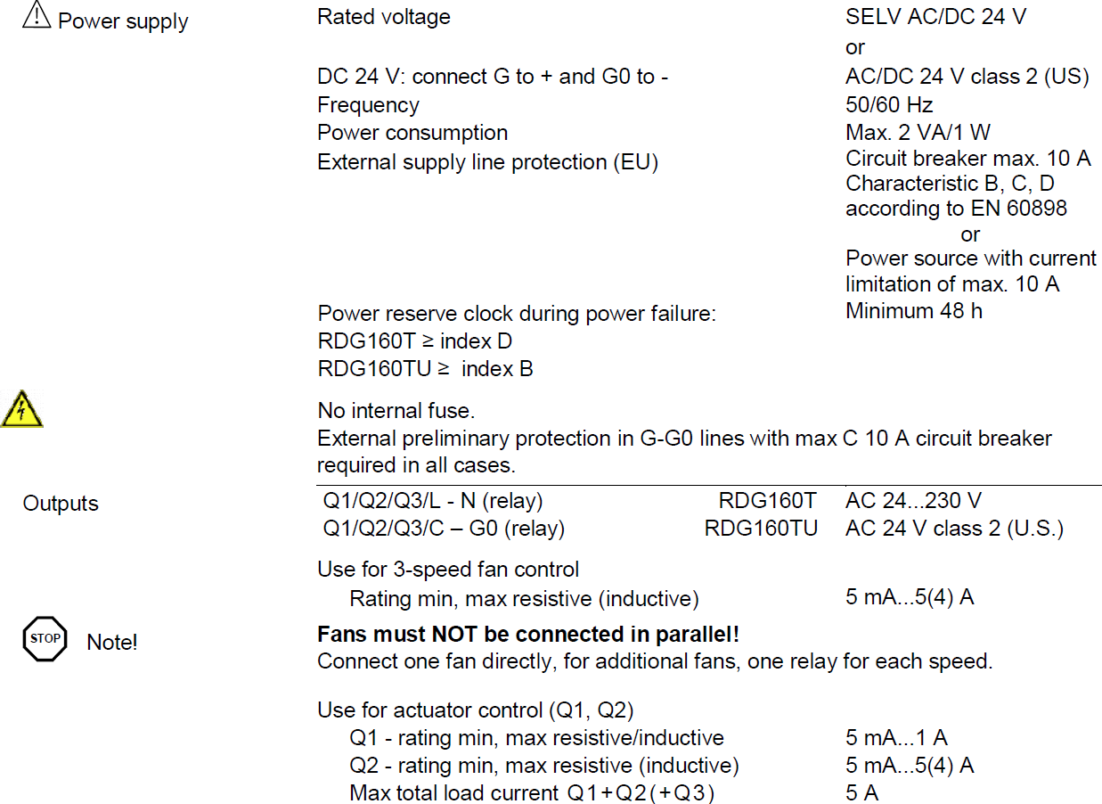
No internal line protection for supply lines to external consumers (Q1, Q2, Q3, Yx or Yxx).
Risk of fire and injury due to short circuits!
- Adapt the line diameters as per local regulations to the rated value of the installed overcurrent protection device.
- The AC 230 V mains or AC 24 V supply line must have a circuit breaker with a rated current of no more than 10 A. For AC 24 V US installations, use Class 2 rated power supplies.
- Properly size the cables to the thermostat, fan and valve actuators for AC 230 V mains voltage.
- Use only valve actuators rated for AC 230 V on RDG100.., RDG110 and on RDG160T if AC 230V is connected to the “L” terminal.
- Use only a 3-speed fan rated with AC 24 V on RDG160TU.
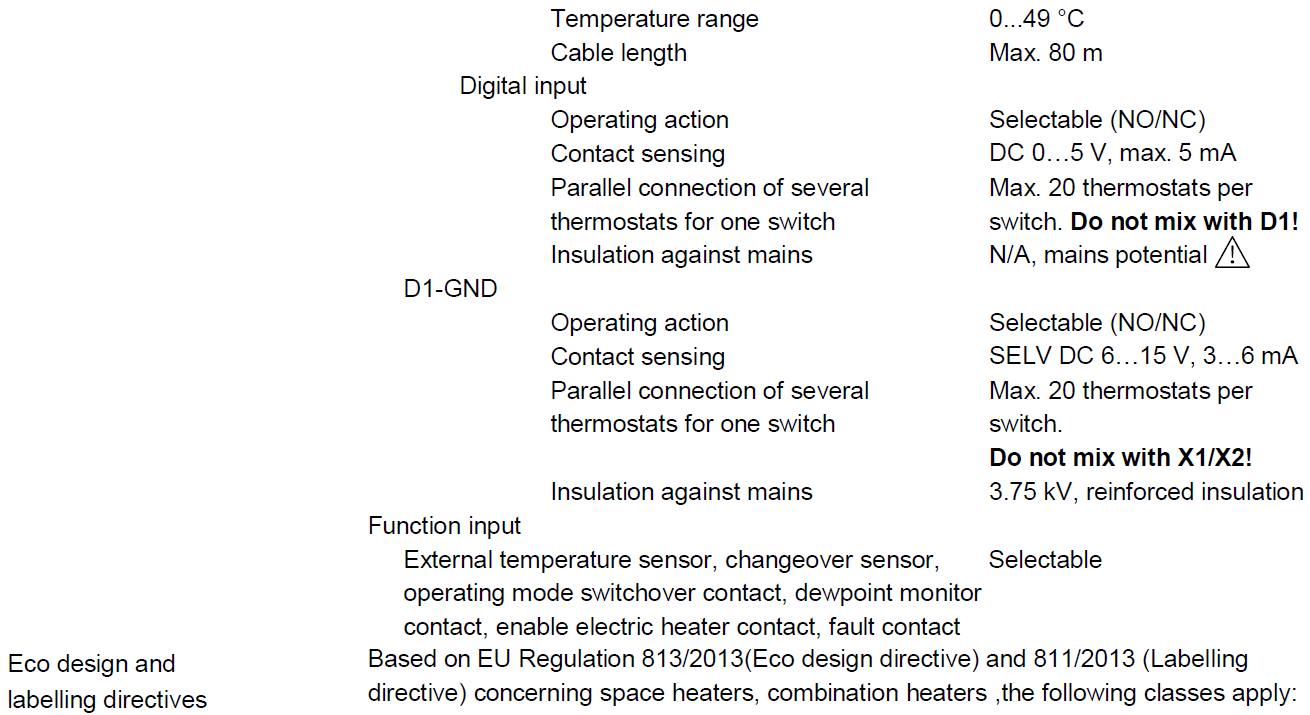
- Isolate the cables of inputs X1-M/X2-M and D1-GND if the conduit box carries
AC 230 V mains voltage. - On the RDG100.. and RDG110, inputs X1-M and X2-M carry mains potential.
If the sensor’s cables are extended, they must be suited for mains voltage. - Inputs X1-M, X2-M or D1-GND of different units (e.g. summer/winter switch) may be connected in parallel with an external switch. Consider overall maximum contact sensing current for switch rating.
- Selectable relay function (RDG160T..). Consider the overall maximum current though the relays.
- Disconnect the power supply before removing the thermostat from the mounting plate!
Commissioning
- Select the application via the DIP switches at the rear of the thermostat before fitting the front housing to the mounting plate.
- Power up the thermostat after successfully connecting the line power. The thermostat starts to reset and all LCD segments flash, indicating that the reset was correct.
After the reset, which takes about 3 seconds, the thermostat is ready for commissioning by qualified HVAC staff. The control parameters of the thermostat can be set to ensure optimum performance of the entire system (see Basic Documentation P3181).
Temperature unit selection wizard (only for RDG110U and RDG160TU): The temperature unit selection wizard enables to select the preferable temperature unit display on thermostat between °C and °F.
- Rotate rotary knob to select the preferable temperature unit.
- Press the button
 (OK) to confirm the selection, and the thermostat goes to normal operating page.
Notes
- Pressing button
 (Esc) does not confirm the temperature unit selection.
 - If the temperature unit is not selected, °C is used by default.
Control sequence
- The control sequence may need to be set via parameter P01 depending on the application. The factory setting for the 2-pipe application is “Cooling only”; and
“Heating and cooling” for the 4-pipe application.
Compressor-based application
- When the thermostat is used in connection with a compressor, the minimum output on-time (parameter P48) and off-time (parameter P49) for Y11/Y21 (RDG110) must be adjusted to avoid damage to the compressor and shorten its life.
Calibrate sensor
- Recalibrate the temperature sensor via parameter P05 if the room temperature displayed on the thermostat does not match the room temperature measured.
Adaptive temperature compensation for el. heating
- If an electric heater is directly connected to output Y21, the load current of the electric heater should be indicated in parameter P46. (RDG110, Index D and higher only). Default setting: 1 A for loads up to 1 A.
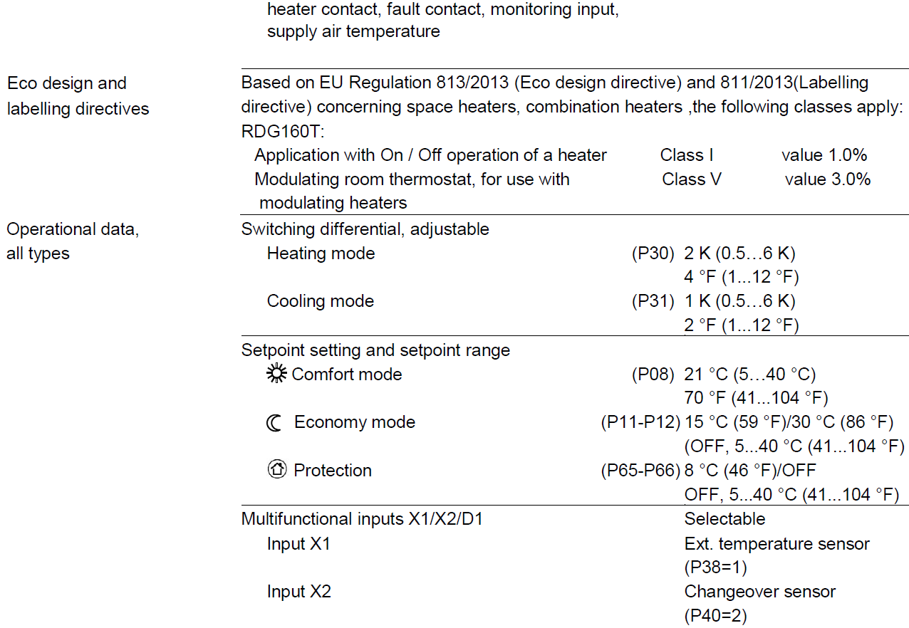
Setpoint and setpoint range limitation
- We recommend reviewing the setpoints and setpoint ranges (parameters P08…P12) and change them as needed to achieve maximum comfort and save energy.
Disposal: The device is considered electrical and electronic equipment for disposal in terms of the applicable European Directive and may not be disposed of as domestic garbage.
- Dispose of the device through channels provided for this purpose.
- Comply with all local and currently applicable laws and regulations.
Technical data
RDG100../RDG110

RDG110U
RDG160T

http://siemens.com/bt/download
Connection terminals
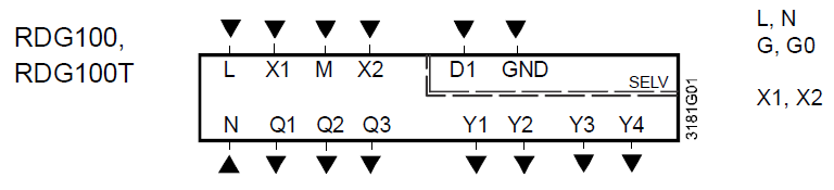
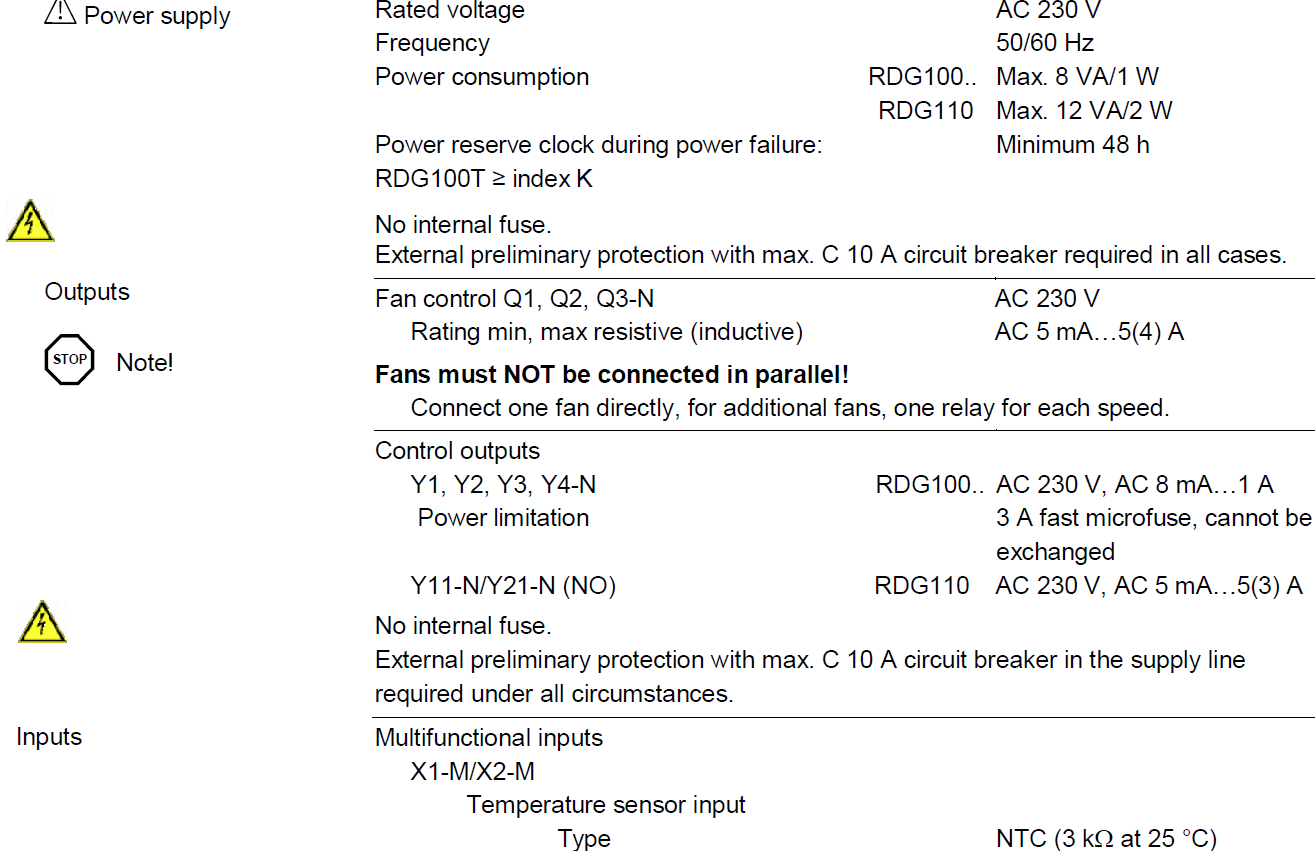
- L, N: Operating voltage AC 230 V
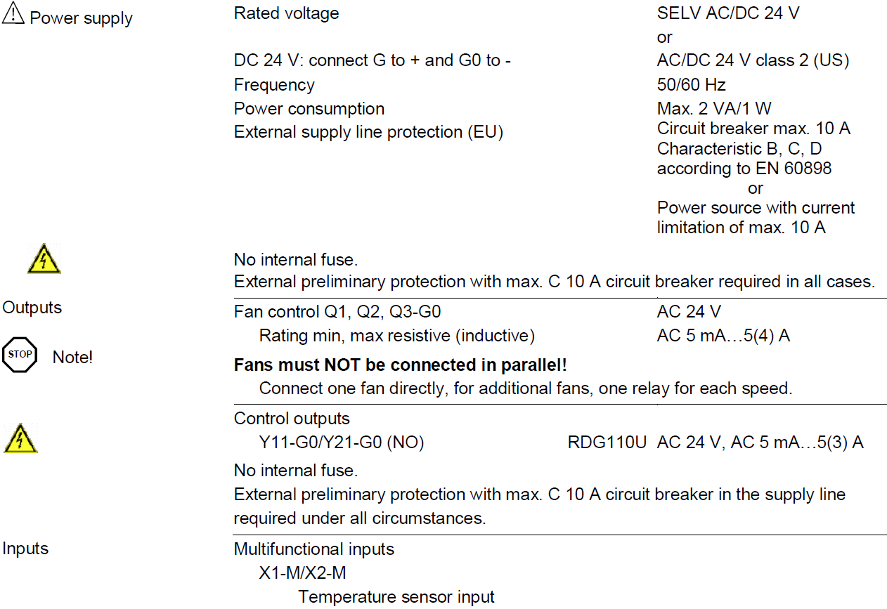
- G, G0: Operating voltage AC/DC 24 V
Note: For DC 24 V: G0 = –; G = + - X1, X2: Multifunctional input for temperature sensor (e.g. QAH11.1) or potential-free switch Factory setting:
- X1: external room temperature sensor
- X2: sensor or switch for heating/cooling changeover
Change of setting: Parameters P38, P40
- M: Measuring neutral for sensor and switch
- D1, GND: Multifunctional input for the potential-free switch.
Factory setting: Operating mode switchover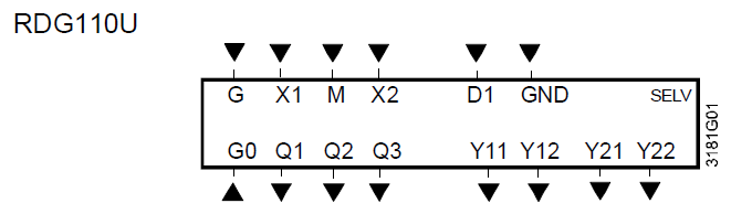
Connection diagrams
- Change of setting: Parameter P42
- Q1: Control output fan speed “low”
- Q2: Control output fan speed “medium”
- Q3: Control output fan speed “high”
- Y1…Y4: Control output “Valve” AC 230 V (NO, for normally open valves), output for electric heater via an external relay
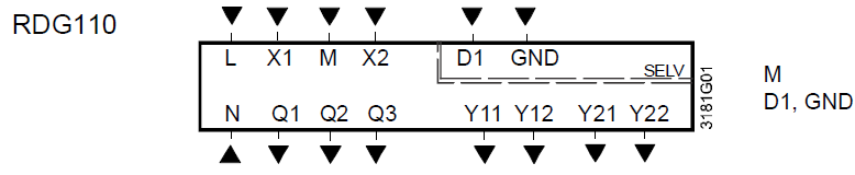
- Y11, Y21: Control output “Valve” AC 230 V for RDG110 Control output “Valve” AC 24 V for RDG110U (NO, for normally open valves), output for compressor or electric heater
- Y12, Y22: Control output “Valve” AC 230 V for RDG110Control output “Valve” AC 24 V for RDG110U (NC, for normally closed valves)
- G, G0: Operating voltage AC/DC 24 V Note: For DC 24 V: G0 = –; G = +
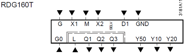
- L (-N): Power supply relay output Q1…3 AC 24…230 V for RDG160T
- Y10, Y20: Control output for DC 0…10 V actuator Y50 Control output “Fan” DC 0…10 V
- Q1…3: Control output fan, valve, el. heater or ex. equipment
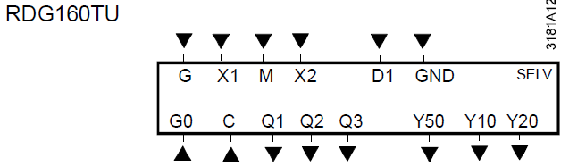
- C (-G0): Power supply relay output Q1…3 AC 24 V for RDG160TU
Connection diagrams
RDG100..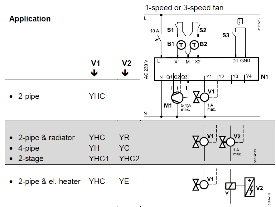
- N1: Room thermostat RDG100..
- M1: 1-speed or 3-speed fan
- V: Valve actuators:
On/Off, heating, cooling, radiator, heating/cooling, 1st or 2nd stage - S1, S2: Switch (keycard, window contact, etc.)
- S3: Switch at SELV input (keycard, window contact)
- B1, B2: The temperature sensor (return air temperature, external room temperature, changeover sensor, floor temperature limit, etc.)
- Q: Relay outputs
- Y1…Y4: Triac outputs
- YH: Heating valve actuator
- YC: Cooling valve actuator
- YHC: Heating/cooling valve actuator
- YR: Radiator valve actuator
- YE: Electric heater with relay/contactor
RDG110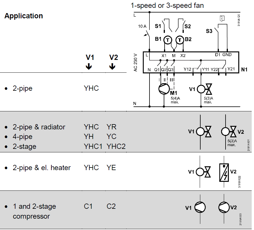
- N1: Room thermostat RDG110
- M1: 1-speed or 3-speed fan
- V: Valve actuators: On/Off, heating, cooling, radiator, heating/cooling, 1st or 2nd stage
- S1, S2: Switch (keycard, window contact, etc.)
- S3: Switch at SELV input (keycard, window contact)
- B1, B2: The temperature sensor (return air temperature, external room temperature, changeover sensor, floor temperature limit, etc.)
- Q: Relay outputs
- Y11…Y22: Relay outputs
- YH: Heating valve actuator
- YC: Cooling valve actuator
- YHC: Heating/cooling valve actuator
- YR: Radiator valve actuator
- YE: Electric heater max. 5 A
- YHC1/YHC2: 1st/2nd stage
- C1/C2: Compressor 1st and 2nd stage
- RV: Reversing valve
RDG110U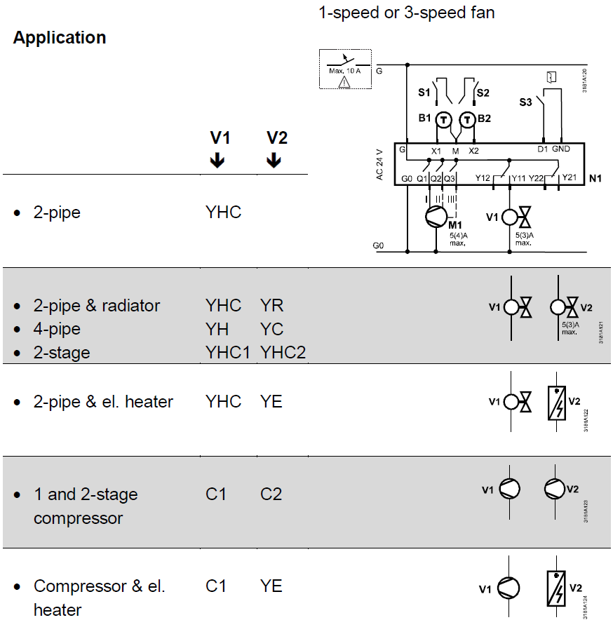
- N1: Room thermostat RDG110U
- M1: 1-speed or 3-speed fan
- V: Valve actuators:
- On/Off, heating, cooling, radiator, heating/cooling, 1st or 2nd stage
- S1, S2: Switch (keycard, window contact, etc.)
- S3: Switch at SELV input (keycard, window contact)
- B1, B2: The temperature sensor (return air temperature, external room temperature, changeover sensor, floor temperature limit, etc.)
- Q: Relay outputs
- Y11…Y22: Relay outputs
- YH: Heating valve actuator
- YC: Cooling valve actuator
- YHC: Heating/cooling valve actuator
- YR: Radiator valve actuator
- YE: Electric heater max. 5 A
- YHC1/YHC2: 1st/2nd stage
- RV: Reversing valve
- C1, C2: Compressor 1st/2nd stage
warning: For US installations, use Class 2-rated power supplies. For other installations, use circuit breakers with rated current of no more than 10 A.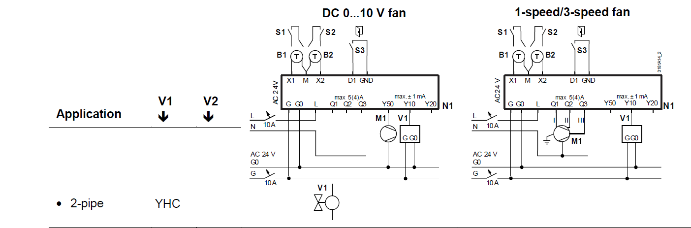
- N1: Room thermostat RDG160T
- S1…S3: Switch (keycard, window contact, presence detector, etc.)
- B1, B2: The temperature sensor (return air temperature, external room temperature, changeover sensor, etc.)
- YE: Electric heater max. 5 A
- C1, C2: Compressor 1st/2nd stage
- M1: 1-speed or 3-speed fan, DC 0…10 V fan
- V1, V2: Valve actuators: On/Off, DC 0…10 V, heating, cooling, radiator, 1st or 2nd stage
- YH: Heating valve actuator
- YC: Cooling valve actuator
- YHC: Heating/cooling valve actuator
- YHC1/YHC2: 1st/2nd stage
- YR: Radiator valve actuator
RDG160TU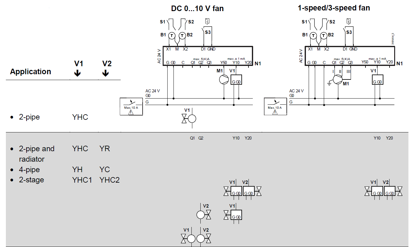
- N1: Room thermostat RDG160TU
- S1…S3: Switch (keycard, window contact, presence detector, etc.)
- B1, B2: The temperature sensor (return air temperature, external room temperature, changeover sensor, etc.)
- YR: Radiator valve actuator
- YE: Electric heater max. 5 A
- M1: 1-speed or 3-speed fan, DC 0…10 V fan
- V1, V2: Valve actuators: On/Off, DC 0…10 V, heating, cooling, radiator, 1st or 2nd stage
- YH: Heating valve actuator
- YC: Cooling valve actuator
- YHC: Heating/cooling valve actuator
- YHC1/YHC2: 1st/2nd stage
warning: For US installations, use Class 2 rated power supplies. For other installations, use circuit breakers with a rated current of no more than 10 A.
Dimensions
© Siemens Switzerland Ltd, 2016 – 2018
Technical specifications and availability are subject to change without notice.
Issued by
- Siemens Switzerland Ltd.
- Building Technologies Division International Headquarters Theilerstrasse 1a
- CH-6300 Zug
- Tel. +41 58 724 2424
- www.siemens.com/buildingtechnologies
REFERENCE:
DOWNLOAD MANUALS:
Leave a Reply