
Siemens RDF870KN Touch Screen Room Controller Thermostat
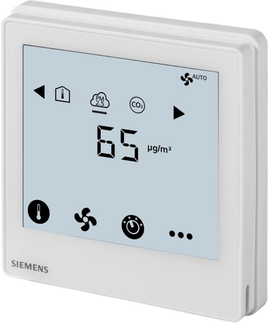
Introduction
| Reference pages | Terminals | Description | |
| RDF870KN | RDF870MB | ||

Application |
L, N
Q1, Q2, Q3, Q4 |
L, N
Q1, Q2, Q3, Q4 |
AC 230 V operating voltage
Fan relay with max four speeds outputs |
 |
X1, X2
M |
X1, X2
M |
Multifunctional inputs 1 & 2
Input reference ground |
| Installation | Y50 | Y50 | DC 0…10 V output |

Parameters |
CE+, CE-
– – |
–
A+, B- REF |
KNX bus + and – terminals Modbus + and – terminals
Modbus reference ground |
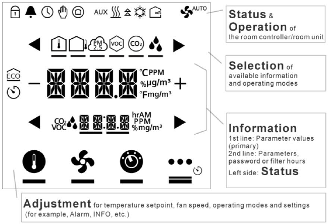
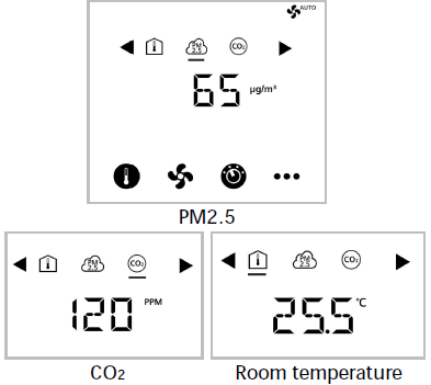
Symbols
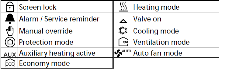
Status symbols
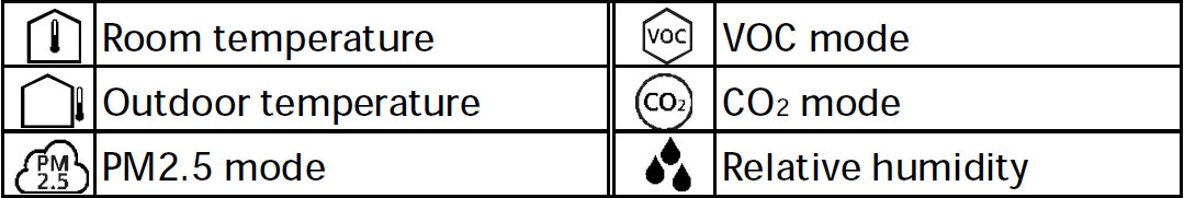
Selection symbols
Operational icons
Commissioning
Download via ETS
Note: This operation applies to RDF870KN only.
![]()
- Screen idle
- Touch digits/screen
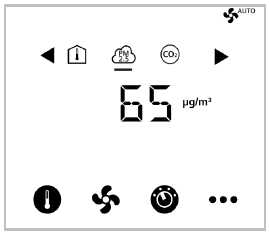
- Normal display

- Touch & hold the icon > 5 s to enter Programming mode
- Ready for downloading address & application
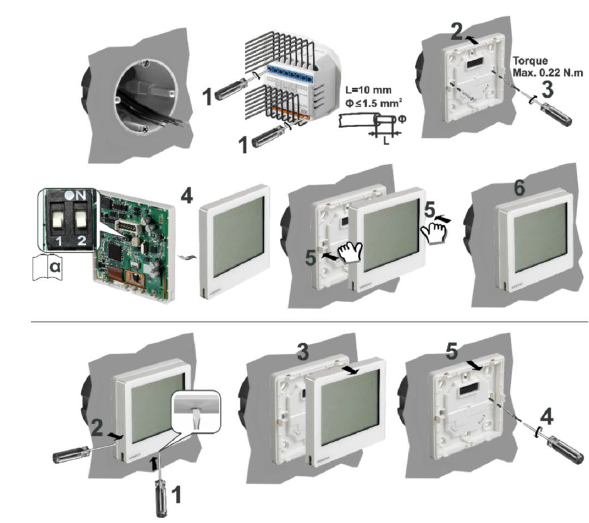
Commissioning: Local via DIP switches
- Set application via DIP switches

- Refer to
- Refer to
- Configure basic control parameters
| DIP switch positions |
Application |
|
| 1 | 2 | |
|
ON |
OFF |
Room unit |
|
OFF |
OFF |
Room controller |
DIP switch setting applies to RDF870MB only.
Current factory setting for PM2.5 control with 3 speed on/off fan application:
- APP= 1: PM2.5 control only
- DISP: Room temp= 1; PM2.5= 1
- SEN1= 3: PM2.5 (AI) μg/m3 (0…10 V)
- SEN2= 0: no function
- FAN= 3: 3 speed fan
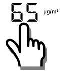
OPERATIONS INSTRUCTIONS
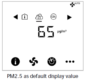
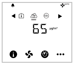
Idle screen shows default PM2.5
![]()
- Screen idle
- Touch digits / screen
- Normal display / mode
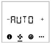
Normal display for ventilation
![]()
- Screen idle

- Touch digits / screen
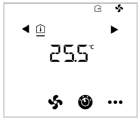
- Normal display / mode
If unit is OFF
![]()
- Screen idle

- Touch digits / screen

- Unit being turned ON
- Normal display / mode
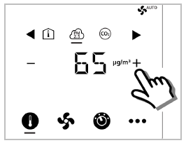
Adjust setpoint
- Touch icon

- Press + or – to adjust:
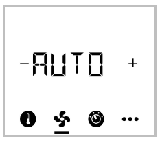
Single fan: On/Off only

- Touch icon
- Press + or – to adjust:
- Change fan mode:
- ON > AUTO
- See for fan type selection.
Fan speed selection
Adjust 3- or 4-speed fan:
- Touch icon
- Press + or – to adjust:
- Auto
- Speed 1
- Speed 2
- Speed 3
- Speed 4
- Depends on fan type selection
- Auto
Adjust ECM fan:
- Touch icon
- Press + or – to adjust:
Fan speed is adjusted by percentage
- Touch + or – once to adjust speed by 5 %.
- Press and hold + or –to quickly adjust speed.
(See Min./Max. settings in Engineering mode parameters)
Dual fan operations
(RDF870MB RU only)
- Touch icon
- Use
 or
or and press + or – to adjust:
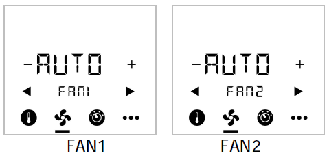
Change operating modes
- Touch icon

- Press + or – to select:
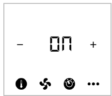
- ON: Comfort mode
- ECO: Economy mode, a
 symbol will be shown
 - OFF: OFF
Adjust timer
(Fan filter alarm)
Change timer setpoint (TCSP) default value:
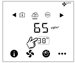
- Touch timer area once to enter time counter setting
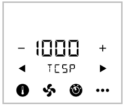
- Press + or – to adjust:
Reset timer:
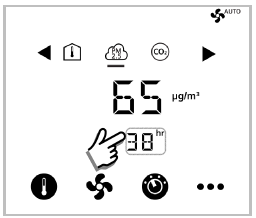
- Press and hold timer area more than 10 s to reset timer to 0.
View alarms
(RDF870KN)
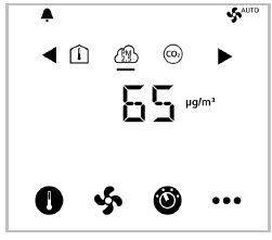
- When alarm bell is displayed

- Touch icon once and press or to view all alarms
View alarms
(RDF870MB)
- When alarm bell is displayed

- Touch icon once and press or to view all alarms
View alarms
(RDF870MB room unit)

- When alarm bell is displayed

- Alarm AL originates in the controller when RDF870MB works as a room unit.
| Priority | Alarm/Service Display | Error code * | Type | Product | |
| 1 | Bus power supply | BUS | 5000 | Fault | RDF870KN |
| 2 | Device address error | Adr | 6001 |
– |
RDF870KN |
| 4 | External fault input 1 | AL1 | 9001 | RDF870.. | |
| 5 | External fault input 2 | AL2 | 9002 | RDF870.. | |
| 6 | Clean filter reminder | FIL | 3911 | RDF870.. | |
| 7 | Internal sensor error | Er1 | – | RDF870.. | |
| 8 | EEPROM error | Er2 | – | RDF870.. | |
| 9 | External error | Er3 | – | RDF870.. | |
- Error codes are for RDF870KN only.
Parameter mode user access

- Touch & hold icon > 5 s
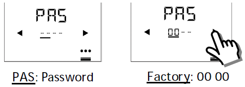
- Enter first password via or

- Enter the second password via or

- After 6 seconds
Note: Press the Setting icon to exit or re-enter the password if not correct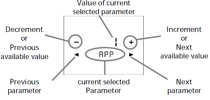
- Edit parameters.
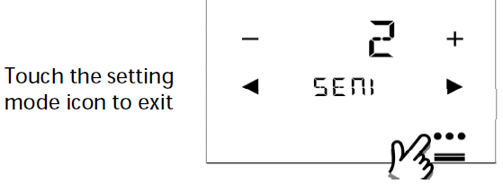
- Exit parameter mode
Engineering parameters
| Item | Description | Range Factory settings | |
| MODA | Modbus address
setting |
1…247 | 1 |
| MODB | Modbus baud rate setting | 1: 9600 bps 2: 19200 bps 3: 38400 bps |
2: 19200 bps |
| MODF | Modbus data frame format | 0: 1/8/E/1 1: 1/8/O/1 2: 1/8/N/1 3: 1/8/N/2 |
0: 1/8/E/1 |
| APP | Application selection | 1: PM2.5 control only 2: PM2.5 + CO2 control 3: CO2 control only 4: Ventilation |
1: PM2.5 control only |
| DISP | Symbol display enable/disable | 0: Disable display 1: Enable display | 1) Room Temp= 1;
2) Outside Temp= 0; 3) PM2.5= 1; 4) VOC= 0; 5) CO2= 0; 6) RH= 0; |
| SEN11) | External sensor1 type selection | 0: No function 1: Temperature (AI) (NTC 10k) 2: Temperature (AI) (0…10 V) 3: PM2.5 (AI) μg/m3 (0…10 V) 4: CO2 (AI) ppm (0…10 V) 5: VOC (AI) % (0…10 V) |
3: PM2.5 (AI)
μg/m3 (0…10 V) |
| 6: VOC (AI) mg/m³ (0…10 V) 7: R.h. (AI) % (0…10 V) 8: Alarm input (DI) 9: Dummy AI (0…10 V) (RU only) 10: Dummy DI (RU only) |
|||
| DIL1 | Operating action if
digital input |
0: Normally open / Open 1: Normally closed / Closed |
0: Normally open /
Open |
| SEN21) | External sensor2 type selection | 0: No function 1: Temperature (AI) (NTC 10k) 2: Temperature (AI) (0…10 V) 3: PM2.5 (AI) μg/m3 (0…10 V) 4: CO2 (AI) ppm (0…10 V) 5: VOC (AI) % (0…10 V) 6: VOC (AI) mg/m³ (0…10 V) 7: R.h. (AI) % (0…10 V) 8: Alarm input (DI) 9: Dummy AI (0…10 V) (RU only) 10: Dummy DI (RU only) |
0: No function |
| DIL2 | Operating action if
digital input |
0: Normally open / Open
1: Normally closed / Closed |
0: Normally open /
Open |
| PMH | PM2.5 sensor high range | Max. of low range…1000 | 500 |
| PML | PM2.5 sensor low
range |
0…Min. of high range | 0 |
| CO2H | CO2 sensor high
range |
Max. of low range…2000 | 2000 |
| CO2L | CO2 sensor low range | 0…Min. of high range | 0 |
| UOCH | VOC sensor high
range |
Max. of low range…100 | 5 |
| UOCL | VOC sensor low
range |
0…Min. of high range | 0 |
| HUMH | Humidity sensor high range | Max. of low range…100 | 100 |
| HUML | Humidity sensor low range | 0…Min. of high range | 0 |
| TEMH | Temperature sensor high range | Max. of low range…100 | 50 |
| TEML | Temperature sensor low range | -50…Min. of high range | 0 |
| SPMH | PM2.5 setpoint high range | Max. of low range…500 | 100 |
| SPML | PM2.5 setpoint low range | 0…Min. of high range | 12 |
| SPCH | CO2 setpoint high
range |
Max. of low range…2000 | 1500 |
| SPCL | CO2 setpoint low
range |
0…Min. of high range | 500 |
| FAN | Fan type selection | 1: 1-speed fan (ON/OFF) 3: 3-speed fan 4: 4-speed fan 5: ECM fan |
3: 3-speed fan |
| ECMH | ECM fan output limit high | Max. of ECML…100 % | 80 % |
| ECML | ECM fan output limit Low | 0…Min. of ECMH | 30 % |
| TC | Filter time display | 0: Disable | 0: Disable |
| setting | 1: Enable | ||
| PMES2) | PM2.5 ECO mode
setpoint |
0…100 | 60 |
| COES2) | CO2 ECO mode
setpoint |
500…1500 | 1000 |
| BUZZ | Buzzer function | 0: Disable 1: Enable |
1: Enable |
| UNIT | Temperature unit | 0: °C (degrees Celsius) 1: °F (degrees Fahrenheit) |
0: °C (degrees Celsius) |
| LOCK | Keylock function | 0: Unlock 1: Locked 2: Setpoint only 3: Operating mode only 4: Setpoint and fan speed only |
0: Unlock |
| OPSL | Operating mode
selection |
0: ON/OFF 1: ON/ECO/OFF 2: ON/ECO/Protection/OFF (RU only) 3: ON/ECO/Protection (room unit only) |
1: ON/ECO/OFF |
| CALT | Internal temperature sensor calibration | -5…5 K | 0 |
RDF870KN available parameters and their order of appearance:
- Room controller:
- APP > DISP > SEN > FAN > OPSL > TC > UNIT > LOCK > BUZZ > CALT > APP
RDF870MB available parameters and their order of appearance:
- Room controller:
- MODA > MODB > MODF >APP > DISP > SEN > FAN > OPSL > TC > UNIT > LOCK > BUZZ > CALT > MODA
- Room unit:
- MODA > MODB > MODF > LOCK > BUZZ > CALT > MODA
- Room controller: 0…8; Room unit: 0…10
- The setpoint cannot be changed in ECO mode.
Restriction for sensor selection:
- If SEN1 and SEN2 are configured with the same selection type 1…8, they cannot be the same sensor types:
- For type 1…8, sensor1 cannot be the same as sensor2.
- For sensor types with the same function such as 1&2 or 5&6, if one sensor type is 1 or 5, the other one cannot be 2 or 6.
Firmware Setpoint Settings
| Item | Description | Range Factory
settings |
|
| TCSP | Filter time setting | 0…9999 | 8760 |
| PM2.5 SP | PM2.5 setpoint | SPML…SPMH | 60 |
| CO2 SP | CO2 setpoint | SPCL…SPCH | 1000 |
| T SP | Temperature setpoint | T SP L…T SP H | 24 |
| T SP H | Temperature setpoint range high | Max. of low range…200 (°C) | 50 |
| T SP L | Temperature setpoint range low | -50…Min. of high range (°C) | 5 |
| VOC SP | VOC setpoint | %: 0…100
mg/m3: 0…5 |
0.6 mg/m3 or
6 % |
| HUM SP | Humidity setpoint | 0…100 % | 50 % |
| P81 1) | Device address (KNX only) | 1…255 | 255 |
1) P81 is only for ETS and local HMI does not support P81:
- During power up, there is a startup delay (TwaitDevice = tWaitMin + DeviceAdr * 200ms) before the processing signal is processed.
- When P81=255(default), the device does not process the signal according to the heartbeat and COV mechanism. But it can respond when another device is polling.
- The local HMI does not support P81.
- When the individual address is changed via ETS, P81 is updated automatically after the device downloads it from ETS.
Expert Mode Parameters
| Item | Description | Range Factory
settings |
|
| PMP | PM2.5 Control factor Xp | 0…1000 | 50 |
| PMI | PM2.5 Control factor Tn | 0…120 min | 45 min |
| CO2P | CO2 control factor Xp | 0…2000 | 100 |
| CO2I | CO2 control factor Tn | 0…120 min | 45 min |
| PMDB | PM2.5 control loop
deadband |
0…20 | 10 |
| CODB | CO2 control loop deadband | 0…100 | 50 |
| OPAF | Operating mode settings after power failure/reset | 0: Return to the previous operating mode/user setting
1: Off |
0: Return to previous operating mode/user
setting |
| FANT | Fan minimum on time (dwell time) | 1…6 min | 2 min |
| FSET | Reload factory settings | 0: OFF = Disable
1: ON = Reload start “–””—””—– ” is displayed while reloading |
0: OFF = Disable |
| SW | Software version | ||
| EPAS | Engineer mode password | 0000…4999 | 0000 |
| XPAS | Expert mode password | 5000…9999 | 9999 |
Room controller workflow:
- EPAS > XPAS > PMP > PMI > PMDB > CO2P > CO2I > CODB > OPAF > FANT > FSET > SW > EPAS
- RDF870MB Room unit workflow: EPAS > XPAS > SW > EPAS
Other Parameters (RDF870MB room unit only)
| Item | Description | Range Factory settings | |
| Output 1 (Q1) | Output for external Modbus
controller (master) |
0: Off
1: On |
0: Off |
| Output 2 (Q2) | Output for external Modbus
controller (master) |
0: Off
1: On |
0: Off |
| Output 3 (Q3) | Output for external Modbus
controller (master) |
0: Off
1: On |
0: Off |
| Output 4 (Q4) | Output for external Modbus
controller (master) |
0: Off
1: On |
0: Off |
For complete parameter list, please refer to the document listed in the following table.
| Ref. | Document title | Document number |
| [1] | Datasheet | A6V11439454 |
Download above document from http://siemens.com/bt/download by searching for the document number.
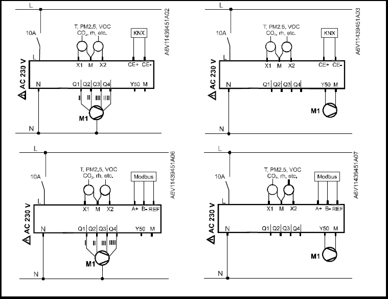
WIRING
RDF870…
- 3/4 Speed Fan and ECM Fan
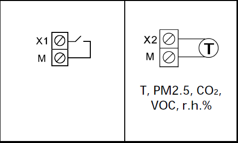
INFO
![]()

![]()
INSTALLATION INSTRUCTIONS
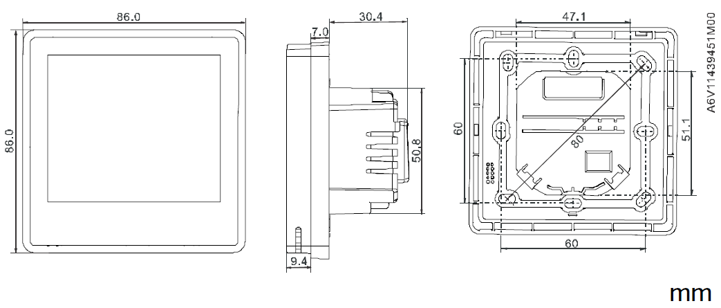
DIMENSION
Issued by
- Siemens Switzerland Ltd
- Smart Infrastructure
- Global Headquarters
- Theilerstrasse 1a CH-6300 Zug
- Tel: +41 58 724 2424
- www.siemens.com/buildingtechnologies
Open Source Software (OSS)

© Siemens Switzerland Ltd, 2019
Technical specifications and availability are subject to change without notice.
REFERENCE:
DOWNLOAD MANUALS:
Siemens RDF870KN Touch Screen Room Controller Thermostat Operating Instruction
Siemens RDF870KN Touch Screen Room Controller Thermostat Operating Instruction
Leave a Reply