
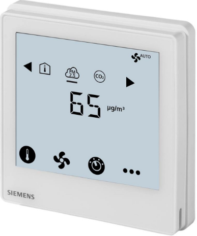
Siemens RDF870KN Touch Screen Room Controller Thermostat
PM2.5 control, CO2 control, or both, and ventilation applications
RDF870KN (KNX) and RDF870MB (Modbus) controllers:
- AC 230 V operating voltage, large, backlit display
- Display and setpoint adjustment for PM2.5 and CO2 control
- Display of room temperature, outside temperature, VOC (volatile organic compound) and r.h. (relative humidity)
- Supports 1-/3-/4-speed On/Off fan or DC fan output
- Two multifunctional inputs for external passive and DC 0…10 V sensors
- Operating modes: Comfort, Economy and Protection
- KNX S-Mode for RDF870KN
- KNX commissioning via ETS or local control parameters
- KNX integration into Design via group (ETS) or individual addressing
- KNX integration into the third-party system via group addressing (ETS)
- RS485 Modbus RTU slave mode for RDF870MB
- Modbus commissioning via a third-party tool, e.g. Modbus scan, Modbus poll, etc.
RDF870MB can be configured as a room unit via DIP switches and it provides the following additional functions:
- Setpoint adjustment and display for room temperature, VOC, RH and display of outside temperature
- Four external outputs via bus and controlled by a master controller
Mounting on recessed square 86 mm box or round 60 mm with 60 mm fixing centers and minimum 40 mm depth
Use
Ventilation control in purifier systems:
Typical applications:
- Residential apartments
- Commercial buildings
- Schools/Universities
- Hospitals/Healthcare centers
Local and remote configuration via one of the following: - Local HMI
- DIP switch selection: room controller or room unit RDF870MB only
- Third-party tool Modbus poll/Modbus scan RDF870MB only
- ETS RDF870KN only
Functions
For room controllers
- Maintain PM2.5 or CO2 level or both via controlling a fan of fresh air units or air purifiers
- Display of room temperature via built-in temperature sensor or bus
- Setpoint adjustment for PM2.5 and CO2 only
- PM2.5 and CO2 values are received from external sensor or via bus.
- CO2 control has higher priority than PM2.5 control if both controls are available.
For room unit
- Display room temperature via built-in sensor in °C
- Display outside temperature via bus or outside sensor input in °C
- Display PM2.5 via bus or outside sensor input in μg/m3
- Display CO2 via bus or outside sensor input in ppm
- Display VOC via bus or outside sensor input in mg/m3 or %
- Display relative humidity via bus or outside sensor input in % r.h.
- Setpoint adjustments for all of the above
Common functionalities
- Selection of operating modes
- Minimum and maximum setpoint limitation
- Fan speed adjustment: Auto, manual (up to 4 speeds)
- Reload factory settings for commissioning, engineering mode and control parameters
Mechanical design
The room controller/room unit consists of the following parts:
- Front panel with electronics, operating elements and built-in room temperature sensor
- Mounting base with power electronics
- The mounting frame is an additional part to complete the installation for RDF870…
Operation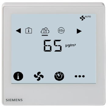
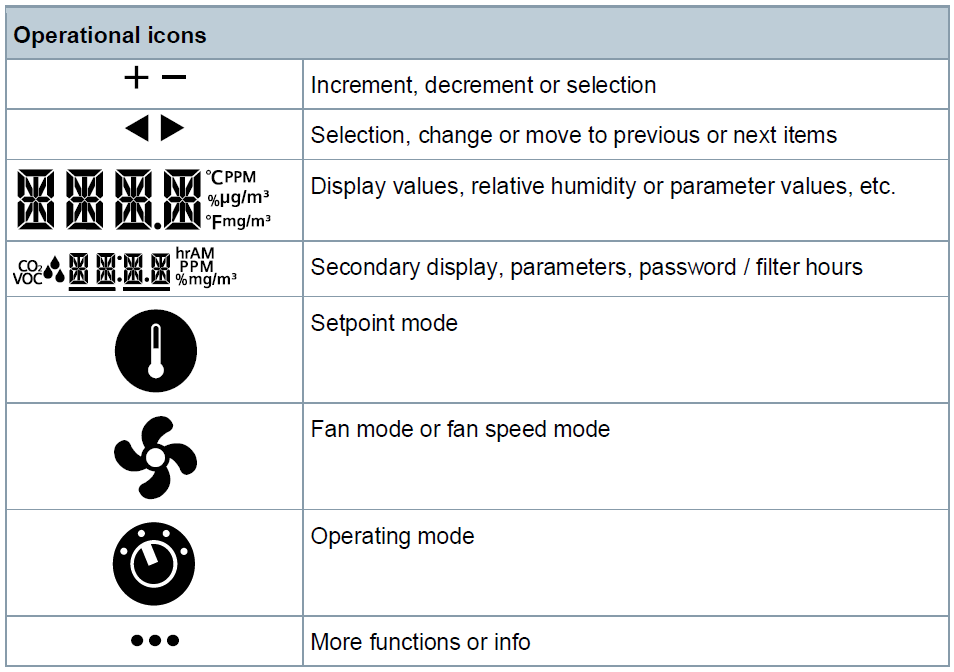
Display
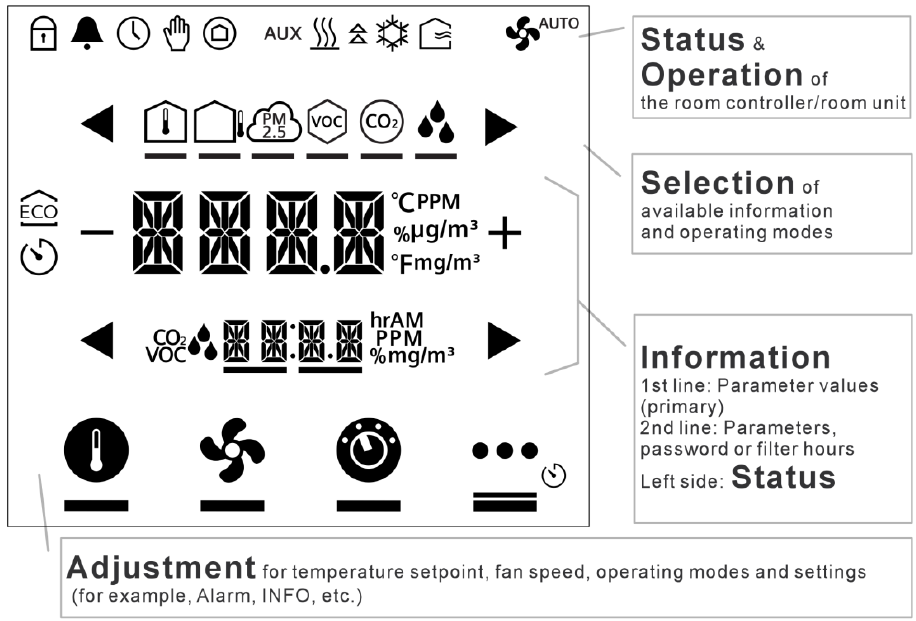
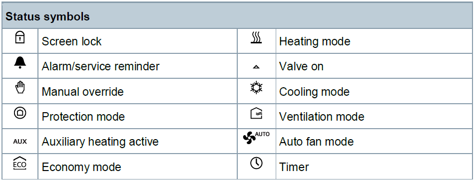
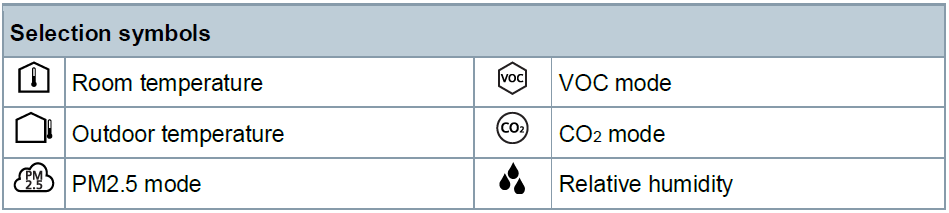
Status symbols
Selection symbols
Operational icons
Type summary
| Product no. | Stock no. | Operating voltage | Control outputs | Suitable for | |
| On/Off | DC 0…10 V | ||||
| RDF870KN | S55770- T407 | AC 230 V | 4 1) | 1 | Square or round conduit box |
| RDF870MB | S55770- T408 | AC 230 V | 4 1) | 1 | Square or round conduit box |
Ordering
- When ordering, indicate product number, SSN, and name. e.g. RDF870KN (S55770-T407) room controller
- Order sensors separately.
Equipment combinations
Sensors
| Type of units | Product number | Data sheet*) | |
| Room sensor for detection of PM2.5
3-color LED service indication |
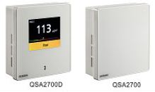 |
QSA2700 | A6V11160938 |
| Room sensor with LCD display for detection of PM2.5
2.4-inch color LCD screen for PM2.5 values, air quality index, and service |
QSA2700D | A6V11160938 | |
| Type of units | Product number | Data sheet*) | |
| Duct air quality sensor CO2/Temperature / rel. humidity / VOC | 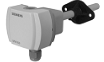 |
QPM1100, QPM2100, QPM2102 | N1962 |
| Duct air quality sensor CO2/Temperature / rel. humidity / VOC | 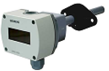 |
QPM2102D | N1962 |
| Duct air quality sensor CO2/Temperature / rel. humidity / VOC | 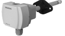 |
QPM2160, QPM2180 | N1962 |
| Duct air quality sensor CO2/Temperature / rel. humidity / VOC | 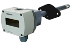 |
QPM2160D, QPM2162D | N1962 |
Product Documentation
Related documents such as environmental declarations, CE declarations, etc., can also be downloaded at the following Internet address: http://siemens.com/bt/download.
| Title | Document ID: |
| Operating instruction | A6V11439451 |
| CE declaration | A5W90010366 (RDF870KN) A5W90010367 (RDF870MB) |
| Environmental product declaration | A6V11625786 |
Notes
CAUTION: National safety regulations
Failure to comply with national safety regulations may result in personal injury and property damage.
- Observe national provisions and comply with the appropriate safety regulations.
Engineering
See the product documentation for information on engineering, selection and sizing connecting cables for supply voltage and field devices.
Mounting and installation
Mount the room controller on a conduit box. Do not mount on a wall in niches or between bookshelves, behind curtains, above or near heat sources, wind outlets or inlets, and do not expose to direct solar radiation. Mount about 1.5 m above the floor.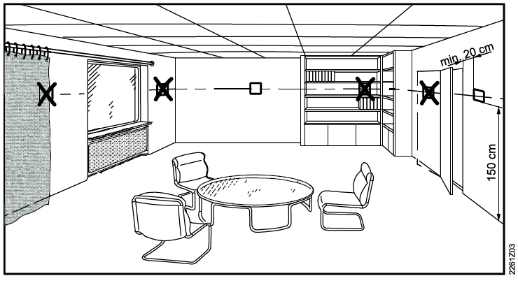
- Do not apply excessive force to screws! Deformation of the mounting frame may result in improper connections and faulty operation.
- Mount the room controller in a clean, dry indoor place without direct airflow from a heating/ cooling device, not exposed to drips or splash water.
- Before removing the front cover, disconnect the power supply.
WARNING No internal line protection for supply lines to external consumers Risk of fire and injury due to short-circuits
- Adapt the line diameters as per local regulations to the rated value of the installed fuse.
See Operating Instruction for the installation instructions enclosed with room controller.
- Comply with local regulations to wire, protect and earth the room controller.
- The device has no internal fuse for supply lines to fan and actuators. To avoid risk of fire and injury due to short circuits, the AC 230 V mains supply line must have a circuit breaker with a rated current of no more than 10 A.
- The wiring cross-section used for the power supply (L, N) and 230 V outputs (Qxx – N) must be adapted to the preceding overload protection elements (max. 10 A) under all circumstances. Always comply with local regulations.
- Properly size the cables to the room controller and valve actuators for AC 230 V mains voltage.
- Cables of SELV inputs X1-M / X2-M: Use cables with min. 230 V insulation, as the conduit box carries AC 230 V mains voltage.
- Inputs X1-M or X2-M of different units (e.g. temperature sensor) may be connected in parallel with an external switch. Consider overall maximum contact sensing current for switch rating.
- KNX communication cables (input CE+ / CE-): Use cables with Min. 230 V insulation, as the conduit box carries AC 230 V mains voltage. (Only for RDF870KN)
- When a KNX bus power supply is connected on the line with communicating room controller and Synco controllers, the internal KNX power supply of the Synco controllers must be switched off. (Only for RDF870KN)
- Isolate the cables of Modbus communication input A+, B- and REF for 230 V. (Only for RDF870MB)
- No cables are provided with a metal shield.
- Disconnect from supply before opening the cover.
Commissioning
After powering up, all LCD segments light up for about three seconds before the room controller enter its normal states. Address and application can be downloaded via ETS by pressing and holding![]() for more than five seconds to enter programming mode. (Only for RDF870KN) The room controller and room unit can be set via DIP switches. (Only for RDF870MB)
for more than five seconds to enter programming mode. (Only for RDF870KN) The room controller and room unit can be set via DIP switches. (Only for RDF870MB)
DIP switch configuration
| DIP switch positions | Application | |
| 1 | 2 | |
| ON | OFF | Room unit |
| OFF | OFF | Room controller |
DIP switch setting applies to RDF870MB only. The current factory setting for PM2.5 control with 3-speed on/off fan application is as follows:
- APP= 1: PM2.5 control only
- DISP: Room temp= 1; PM2.5= 1
- SEN1= 3: PM2.5 (AI) μg/m3 (0…10 V)
- SEN2= 0: no function
- FAN= 3: 3-speed fan
Software version (RDF870KN)
Two different software versions of RDF870KN are available:
- RDF870KN with software version (U101): Related ETS5 file (RDF870KN_v1d0_ETS5.knxprod)
- RDF870KN with software version (U103): Related ETS5 file (RDF870KN_v1d1_ETS5.knxprod)
The software version can be checked as follows:
- The software version relates to the production date (DDMMYYYY) on the individual package label or printed on the rear of the product.
E.g. “DDMMYYYY = 02062019” equals “02 June 2019”- If YYYY = 2018, 2019 or 2020, the RDF870KN software version is “U101”.
- IF YYYY = 2021 onwards, the RDF870KN software version is “U103”.
- Checked under parameter mode:
- Enter password 9999 after accessing parameter mode. For parameter mode access, see Parameter mode user access.
- When the first parameter appears, press and hold
 until “SW” is displayed. Then related software version is shown as “U101” or “U103”.
Note For further support, please raise a support request via the site: https://support.industry.siemens.com/cs.
Disposal
The device is considered an electronic device for disposal in accordance with European Guidelines and may not be disposed of as domestic garbage.
- Dispose of the device through channels provided for this purpose.
- Comply with all local and currently applicable laws and regulations.
Warranty
Technical data on specific applications are valid only together with Siemens products listed under “Equipment combinations”. Siemens rejects any and all warranties in the event that third-party products are used.
Technical data
| Power supply | |
| Operating voltage | AC 230 V |
| Frequency | 50/60 Hz. |
| Power consumption | Max. 7.0 VA / 2.5 W |
CAUTION On internal fuse.
External preliminary line protection with max. C 10 A circuit breaker is required in all cases.
| Multifunctional input X1-M/X2-M | |
| Temperature sensor input: Type Temperature range Accuracy Calibration range |
NTC 10k 0…50 °C (32…122 °F) ±0.5 K at 25 °C (77 °F) -5 K…5 K, resolution 0.5 K |
| Digital Input: Logic states Insulation against mains voltage (SELV) Cable length |
Selectable NO/NC ≥3.75 kV, reinforced insulation Up to 80 m (wire diameter of 1.5 mm2)) |
| Analog input Signal type Sensor range and limit Cable length |
0…10 V, NTC 10k Set by parameters Up to 80 m (wire diameter of 1.5 mm2)) |
| Function of inputs PM2.5 sensor, CO2 sensor, VOC sensor, humidity sensor, alarm input |
Selectable X1: SEN1 X2: SEN2 |
| Output | |
| 3/4 speed fan | Q1…Q4 |
| Type | On/Off |
| Voltage | AC 230 V |
| Maximum current | 5(2) A |
| ECM fan | Y50 |
| Type | Modulating |
| Voltage | DC 0…10 V |
| Maximum current | 5.0 mA |
CAUTION If fans must be connected in parallel, connect one fan directly, for additional fans, one relay for each speed.
| KNX interface | |
| KNX type Bus current | KNX TP1-64, galvanic isolation. 5 mA |
| Modbus interface | |
| Modbus type | RS485 |
| Transmit mode | RTU |
| Connection | Support up to 32 |
| Baud rate | 9600, 19200 (default), 38400 |
| Modbus address | 1-247, 1 (default) |
| Cable length | Max.1200 meters |
| Identity | Slave |
| Transmission format (start bit – data – parity | 0 = 1-8-E-1 (default) / 1 = 1-8-O-1 / 2 = 1-8- |
| – stop) | N-1 / 3 = 1-8-N-2 |
| Wiring connections | |
| Diameter Wire | 1.5 mm2 Solid or stranded |
| Ambient Conditions and protection classification | |
| Classification as per EN 60730
Function of automatic control devices Degree of contamination Overvoltage category |
Type 1
2 III |
| Design type | Device suited for use with equipment of safety class II. |
| Degree of protection of housing to EN 60529 Room automation station
With terminal cover |
IP30. IP30. |
| Climatic ambient conditions
Transport (packaged for transport) as per EN 60721-3-2 Operation as per EN 60721-3-3. |
Class 2K3 Class 3K5 1) |
| Mechanical ambient conditions
Transport as per EN 60721-3-2 Operation as per EN 60721-3-3 |
Class 2M2. Class 3M2. |
| Standards, directives and approvals | |
| Electromagnetic compatibility | For residential, commercial, and industrial environments |
| EU conformity (CE) | A5W90010366 (RDF870KN) *)
A5W90010367 (RDF870MB) *) |
| Standards, directives and approvals | |
| RCM conformity | A5W90010386 (RDF870KN) *)
A5W90010387 (RDF870MB) *) |
| REACH | Regulation (EC) No 1907/2006 Registration, Evaluation, Authorisation and Restriction of Chemicals (REACH) |
| RoHS | Directive 2011/65/EU restriction of the use of certain hazardous substances in electronic equipment |
| Environmental compatibility | The product environmental declaration (A6V11625786 *) contains data on environmentally compatible product design and assessments (RoHS compliance, materials composition, packaging, environmental benefit, disposal). |
| General | |
| Weight without/with package | 165 g / 265 g |
| Housing front color | Ivory white |
| Housing flammability class according to UL94 | V-0 |
The documents can be downloaded from http://siemens.com/bt/download.
Diagrams
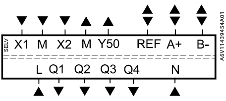
Connection terminals
| RDF870KN | RDF870MB | |
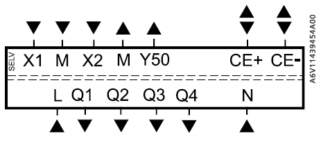 |
 |
|
| X1 | Multifunction input 1 | |
| M | Input reference ground for X1, X2 and Y50 | |
| X2 | Multifunction input 2 | |
| Y50 | DC 0…10 V output | |
| CE+, CE- | KNX bus + and – terminals | |
| REF | Modbus reference ground | |
| A+, B- | Modbus + and – terminals | |
| L, N | AC 230 V operating voltage | |
| Q1 | Output, fan speed 1, AC 230 V | |
| Q2 | Output, fan speed 2, AC 230 V | |
| Q3 | Output, fan speed 3, AC 230 V | |
| Q4 | Output, fan speed 4, AC 230 V | |
Connection diagrams
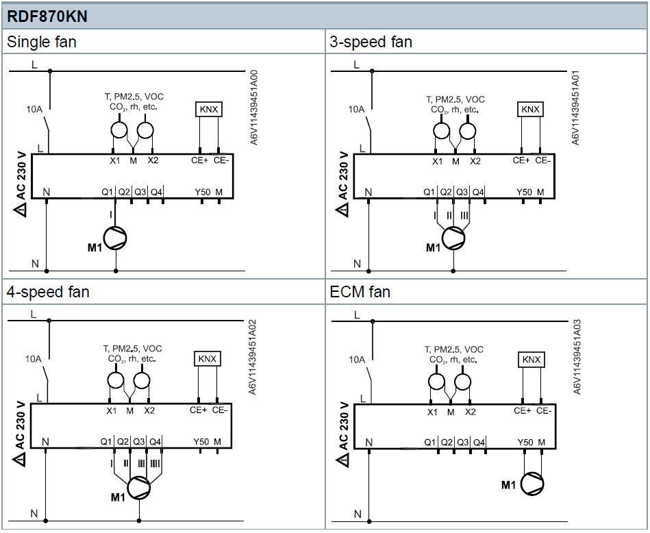
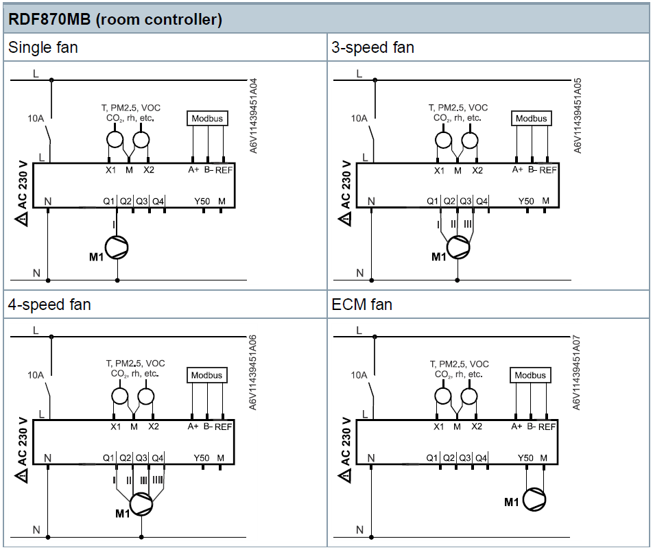
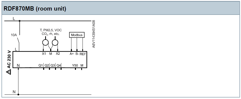
| L, N | AC 230 V operating voltage |
| X1, X2 | Multifunctional inputs 1 & 2 (sensor, alarm, etc.) |
| M | Input reference ground for X1, X2 and Y50 |
| CE+, CE- | KNX bus + and – terminals |
| Q1, Q2, Q3, Q4 | Four speeds fan output (relay output) |
| Y50 | DC 0…10 V output |
| REF | Modbus reference ground |
| A+, B- | Modbus + and – terminals |
| M1 | 1-speed, 3-speed or 4-speed fan, DC 0…10 V fan |
Application examples
CO2 application (single duct single fan)
Single duct single fan fresh air unit or purifier with a built-in PM2.5 filter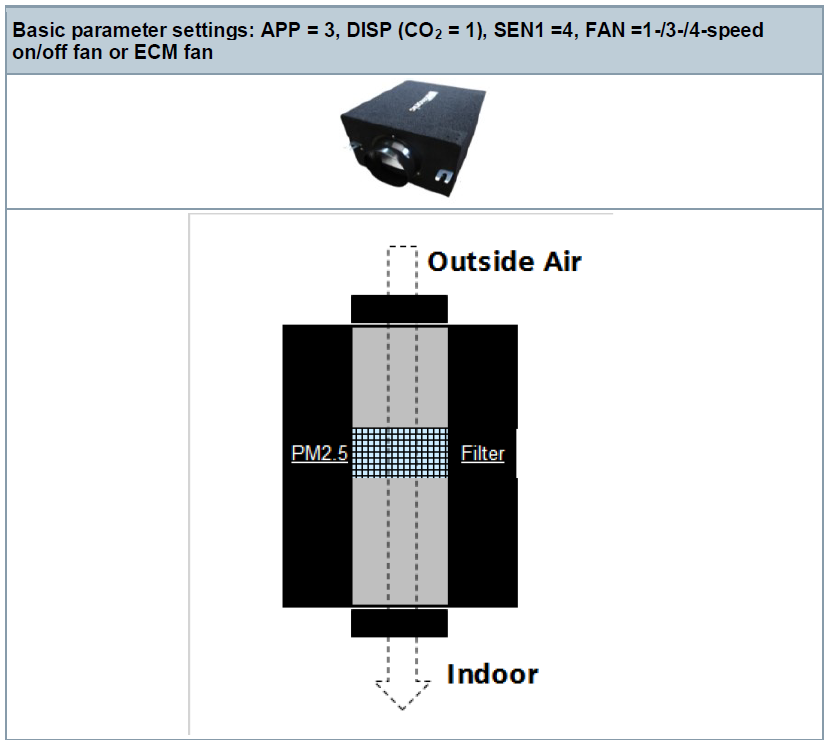
RDF870… unit can be set up as a CO2 controller with an external CO2 sensor connected to X1 to control the fan for a fresh air unit (i.e. single duct single fan fresh air unit with/without PM2.5 built-in filter).
The fan speeds are switched as per the actual CO2 level and the CO2 setpoint. The built-in PM2.5 filter already purifies the outside air before entering indoors.
PM2.5 application (single duct single fan)
Single duct single fan purifier with built-in PM2.5 filter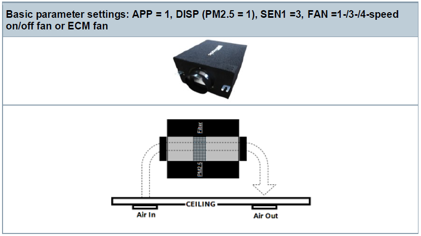
RDF870… unit can be set up as a PM2.5 controller with an external PM2.5 sensor connected to X1 to control the fan for a PM2.5 purifier unit (i.e. single duct single fan purifier with PM2.5 built-in filter).
The purifier is not connected to external but installed on the ceiling. The purifier circulates in-door through its built-in PM2.5 filter. The fan speeds are switched as per the actual PM2.5 level and the PM2.5 setpoint.
CO2 application (dual duct parallel connected fan)
Dual duct parallel connected fan fresh air unit or purifier with a built-in PM2.5 filter
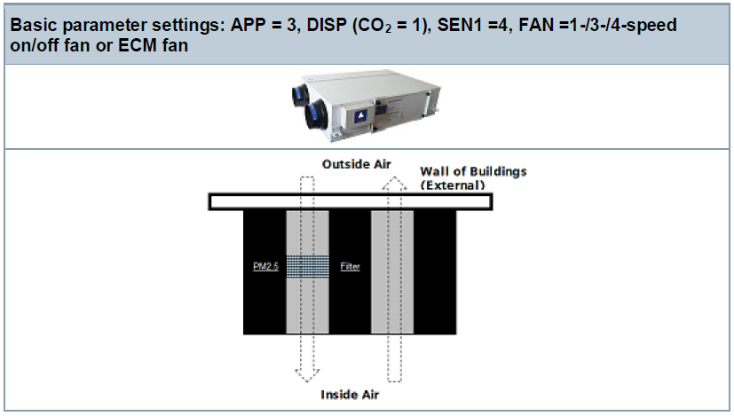
RDF870… unit can be set up as a CO2 controller with an external CO2 sensor connected to X1 to control the fan operation of a fresh air unit (i.e. dual duct parallel connected fan fresh air unit with/without PM2.5 built-in filter).
- The fan speeds are switched as per the actual CO2 value and the CO2 setpoint.
- The built-in PM2.5 filter already purifies the outside air before entering indoors.
- This fresh air unit operates in a similar way as per single duct type. With the dual duct type, air exchange performance is better.
CAUTION If fans must be connected in parallel, connect one fan directly, for additional fans, one relay for each speed.
PM2.5 & CO2 room unit application (dual duct independent fan control together with a master controller)
Dual duct independent fan fresh air unit or purifier with built-in PM2.5 filter via by-pass damper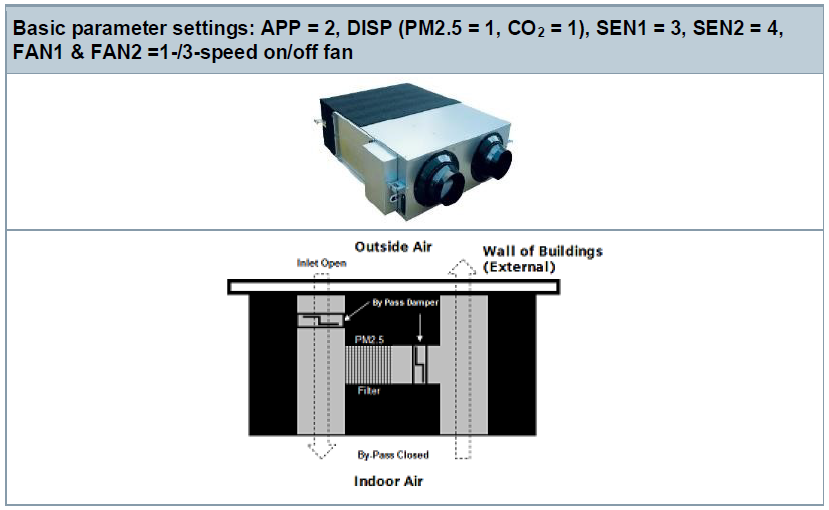
RDF870… unit can be set up as a controller combining PM2.5 and CO2 control with an external PM2.5 and CO2 sensors connected to X1 and X2 respectively to control the fan for a fresh air unit and purifier (i.e. dual duct independent fan fresh air unit with PM2.5 built-in filter via by-pass damper). The damper can be disabled (inlet open and by-pass close) or enabled (by-pass open) via an extra damper input from a master controller. When the by-pass damper is inactive, the outside air can enter the room via the inlet that is controlled by a master. The fan speeds are switched as per the actual CO2 level and the CO2 setpoint.
When the by-pass damper is active via control input from a master controller, the inlet is disabled by the master controller, and outside air is blocked. As a result, all the exhaust air (or partially) will be forced to flow via the bypass PM2.5 filter and return to the room– air circulates internally. The fan speeds are switched as per the actual PM2.5 level and the PM2.5 setpoint. If both fans have the same fan speed, airflow circulates internally. However, two fans also can be operated at different speeds to generate different air pressures internally.
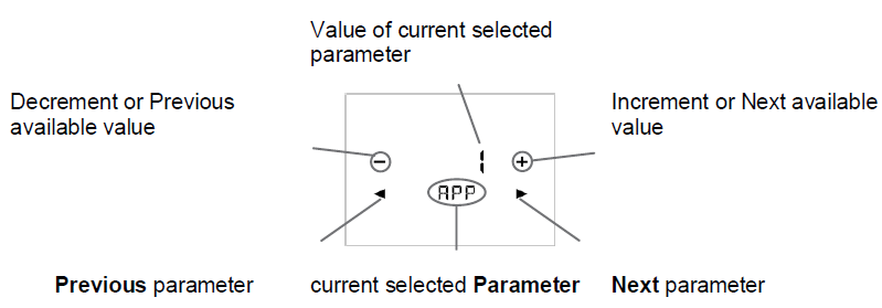
Parameters
Parameter mode user access![]()
![]()
- Touch & hold icon > 5 s

- Enter first password via or
 .
.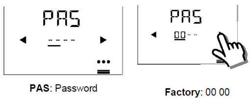
- Enter the second password via or.

- After 6 seconds

- Edit parameters
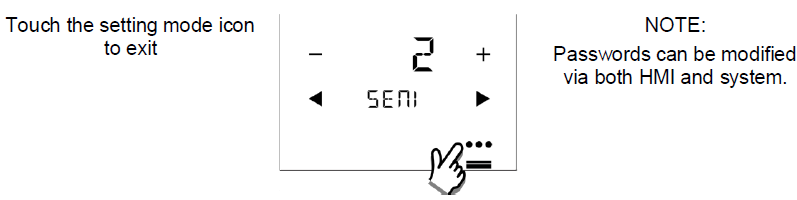
- Exit parameter mode
Engineering parameters
| Item | Description | Range | Factory settings |
| MODA | Modbus address setting | 1…247 | 1 |
| MODB | Modbus baud rate setting | 1: 9600 bps 2: 19200 bps 3: 38400 bps |
2: 19200 bps |
| MODF | Modbus data frame format | 0: 1/8/E/1 1: 1/8/O/1 2: 1/8/N/1 3: 1/8/N/2 |
0: 1/8/E/1 |
| APP | Application selection | 1: PM2.5 control only 2: PM2.5 + CO2 control 3: CO2 control only 4: Ventilation |
1: PM2.5 control only |
| DISP | Symbol display enable/disable | 0: Disable display 1: Enable display |
1) Room temp= 1; 2) Outside temp= 0; 3) PM2.5= 1; 4) VOC= 0; 5) CO2= 0; 6) RH= 0; |
| SEN1 1) | External sensor1 type selection | 0: No function 1: Temperature (AI) (NTC 10k) 2: Temperature (AI) (0…10 V) 3: PM2.5 (AI) μg/m3 (0…10 V) 4: CO2 (AI) ppm (0…10 V) 5: VOC (AI) % (0…10 V) 6: VOC (AI) mg/m³ (0…10 V) 7: R.h. (AI) % (0…10 V) 8: Alarm input (DI) 9: Dummy AI (0…10 V) (RU only) 10: Dummy DI (RU only) |
3: PM2.5 (AI) μg/m3 (0…10 V) |
| DIL1 | Control action if digital input | 0: Normally open / Open 1: Normally closed / Closed |
0: Normally open / Open |
| SEN2 1) | External sensor2 type selection | 0: No function 1: Temperature (AI) (NTC 10k) 2: Temperature (AI) (0…10 V) 3: PM2.5 (AI) μg/m3 (0…10 V) 4: CO2 (AI) ppm (0…10 V) 5: VOC (AI) % (0…10 V) 6: VOC (AI) mg/m³ (0…10 V) 7: R.h. (AI) % (0…10 V) 8: Alarm input (DI) 9: Dummy AI (0…10 V) (RU only) 10: Dummy DI (RU only) |
0: No function |
| DIL2 | Control action if digital input | 0: Normally open / Open
1: Normally closed / Closed |
0: Normally open / Open |
| PMH | PM2.5 sensor high range | Max. of low range…1000 | 500 |
| PML | PM2.5 sensor low range | 0…Min. of high range | 0 |
| CO2H | CO2 sensor high range | Max. of low range…2000 | 2000 |
| CO2L | CO2 sensor low range | 0…Min. of high range | 0 |
| UOCH | VOC sensor high range | Max. of low range…100 | 5 |
| UOCL | VOC sensor low range | 0…Min. of high range | 0 |
| HUMH | Humidity sensor high range | Max. of low range…100 | 100 |
| HUML | Humidity sensor low range | 0…Min. of high range | 0 |
| Item | Description | Range | Factory settings |
| TEMH | Temperature sensor high range | Max. of low range…100 | 50 |
| TEML | Temperature sensor low range | -50…Min. of high range | 0 |
| SPMH | PM2.5 setpoint high range | Max. of low range…500 | 100 |
| SPML | PM2.5 setpoint low range | 0…Min. of high range | 12 |
| SPCH | CO2 setpoint high range | Max. of low range…2000 | 1500 |
| SPCL | CO2 setpoint low range | 0…Min. of high range | 500 |
| FAN | Fan type selection | 1: 1-speed fan (ON/OFF) 3: 3-speed fan 4: 4-speed fan 5: ECM fan |
3: 3-speed fan |
| ECMH | ECM fan output limit high | Max. of ECML…100 % | 80 % |
| ECML | ECM fan output limit low | 0…Min. of ECMH | 30 % |
| TC | Filter time display setting | 0: Disable
1: Enable |
0: Disable |
| PMES 2) | PM2.5 ECO mode setpoint | 0…100 | 60 |
| COES 2) | CO2 ECO mode setpoint | 500…1500 | 1000 |
| BUZZ | Buzzer function | 0: Disable 1: Enable |
1: Enable |
| UNIT | Temperature unit | 0: °C (degrees Celsius) 1: °F (degrees Fahrenheit) |
0: °C (degrees Celsius) |
| LOCK | Keylock function | 0: Unlock 1: Locked 2: Setpoint only 3: Operating mode only 4: Setpoint and fan speed only |
0: Unlock |
| OPSL | Operating mode selection | 0: ON/OFF 1: ON/ECO/OFF 2:ON/ECO/Protection/OFF (RU only) 3: ON/ECO/Protection (room unit only) |
1: ON/ECO/OFF |
| CALT | Internal temperature sensor calibration | -5…5 K | 0 |
RDF870KN available parameters and their order of appearance:
- Room controller: APP > DISP > SEN > FAN > OPSL > TC > UNIT > LOCK > BUZZ > CALT > APP RDF870MB available parameters and their order of appearance:
- Room controller: MODA > MODB > MODF >APP > DISP > SEN > FAN > OPSL > TC > UNIT > LOCK > BUZZ > CALT > MODA
- Room unit: MODA > MODB > MODF > LOCK > BUZZ > CALT > MODA
- Room controller: 0…8; Room unit: 0…10
- The setpoint cannot be changed in ECO mode.
Restriction for sensor selection:
- If SEN1 and SEN2 are configured with the same selection type 1…8, they cannot be the same sensor types:
- For type 1…8, sensor1 cannot be the same as sensor2.
- For sensor types with the same function such as 1&2 or 5&6, if one sensor type is 1 or 5, the other one cannot be 2 or 6.
Note: When APP = 2 (both PM2.5 and CO2 control) is selected, FAN = 1 or 3 only.
Firmware setpoint settings
| Item | Description | Range | Factory settings |
| TCSP | Filter time setting | 0…9999 | 8760 |
| PM2.5 SP | PM2.5 setpoint | SPML…SPMH | 60 |
| CO2 SP | CO2 setpoint | SPCL…SPCH | 1000 |
| T SP | Temperature setpoint | T SP L…T SP H | 24 |
| T SP H | Temperature setpoint range high | Max. of low range…200 (°C) | 50 |
| T SP L | Temperature setpoint range low | -50…Min. of high range (°C) | 5 |
| VOC SP | VOC setpoint | %: 0…100 mg/m3: 0…5 | 0.6 mg/m3 or 6 % |
| HUM SP | Humidity setpoint | 0…100 % | 50 % |
| P81 1) | Device address (KNX only) | 1…255 | 255 |
- During power-up, there is a startup delay (TwaitDevice = tWaitMin + DeviceAdr * 200ms) before the processing signal is processed.
- When P81=255 (default), the device does not process the signal according to the heartbeat and COV mechanism. But it can respond when another device is polling.
- The local HMI does not support P81.
- When the individual address is changed via ETS, P81 is updated automatically after the device downloads it from ETS.
Expert mode parameters
| Item | Description | Range | Factory settings |
| PMP | PM2.5 control factor Xp | 0…1000 | 50 |
| PMI | PM2.5 Control factor Tn | 0…120 min | 45 min |
| CO2P | CO2 control factor Xp | 0…2000 | 100 |
| CO2I | CO2 control factor Tn | 0…120 min | 45 min |
| PMDB | PM2.5 control loop deadband | 0…20 | 10 |
| CODB | CO2 control loop deadband | 0…100 | 50 |
| OPAF | Operating mode settings after power failure/reset | 0: Return to the previous operating mode/user setting
1: Off |
0: Return to the previous operating mode/user setting |
| FANT | Fan minimum on time | 1…6 min | 2 min |
| FSET | Reload factory settings | 0: OFF = Disable 1: ON = Reload start“–”“—”“—– ” is displayed while reloading |
0: OFF = Disable |
| SW | Software version | ||
| EPAS | Engineer mode password | 0000…4999 | 0000 |
| XPAS | Expert mode password | 5000…9999 | 9999 |
Room controller workflow: EPAS > XPAS > PMP > PMI > PMDB > CO2P > CO2I > CODB > OPAF > FANT > FSET > SW > EPAS RDF870MB Room unit workflow: EPAS > XPAS > SW > EPAS
Other parameters (RDF870MB room unit only)
| Item | Description | Range | Factory settings |
| Output 1 (Q1) | Output for external Modbus controller (master) | 0: Off
1: On |
0: Off |
| Output 2 (Q2) | Output for external Modbus controller (master) | 0: Off
1: On |
0: Off |
| Output 3 (Q3) | Output for external Modbus controller (master) | 0: Off
1: On |
0: Off |
| Output 4 (Q4) | Output for external Modbus controller (master) | 0: Off
1: On |
0: Off |
KNX S-Mode communication objects (RDF870KN)
Overview
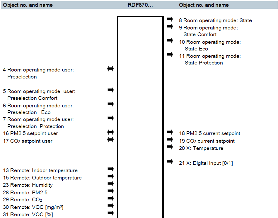
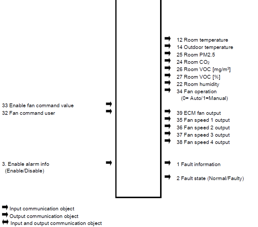
Description of communication objects
| Object no. | Object name | Function | Type/length | Flags |
| 1 | Fault information | Alarm information | 219.001
6 Byte |
CT |
| Common alarm output. If an alarm occurs, the alarm number is transmitted. | ||||
| 2 | Fault state | Faulty/normal | 1.005
1 bit |
CT |
| Common alarm output. If an alarm occurs, the alarm flag is set. | ||||
| 3 | Enable alarm info | Enable/disable | 1.003
1 bit |
CWU |
| A supervisor alarm system can disable the broadcasting of alarms by the devices. This has no impact on the local display of alarms. After a timeout of 48 hours, the sending of faults is automatically enabled again. | ||||
| 4 | Room operating mode user: Preselection | Comfort Economy OFF | 20.102
1 Byte |
CWTU |
| Controls the room operating mode selection of the room controller/room unit via bus. The command can also be submitted as three 1-bit communication objects (5…7). The last interaction wins-either from the local operating mode button or via bus. Note: 8-bit and 1-bit objects available, selectable by using parameters in ETS |
||||
|
5 6 7 |
Operating mode user: Preselection
– Comfort – Eco – Protection |
ON OFF | 1.001
1 bit |
CW |
| Switch room operating mode to either Comfort, Economy or OFF. The last interaction wins – either from local operating mode button or via bus. Note: 8-bit and 1-bit object available, selectable by using parameters in ETS |
||||
| 8 | Room operating mode: State | Comfort Economy Off | 20.102
1 Byte |
CRT |
| Effective room operating mode used by the thermostat (considering timer, user selection, etc.) This state information is available via one 8-bit enumeration or three 1-bit communication objects (9…11). Note: 8-bit and 1-bit object available, selectable by using parameters in ETS |
||||
|
9 10 11 |
Room operating mode:
– State Comfort – State Eco – State Protection |
ON OFF | 1.001
1 bit |
CT |
| The corresponding communication object sends “True” Note: 8-bit and 1-bit object available, selectable by using parameters in ETS |
||||
| 12 | Room temperature | Temperature value | 9.001
2 Bytes |
CRT |
| Value of the room temperature.
Note: The room temperature value is decided by priority if all value types exist. (Built-in > Remote) |
||||
| 13 | Remote: Indoor temperature | Temperature value | 9.001 2 Bytes |
CWU |
| Remote indoor temperature sensor value | ||||
| 14 | Outdoor temperature | Temperature value | 9.001 2 Bytes |
CRT |
| Value of the outside temperature is received. | ||||
| Object no. | Object name | Function | Type/length | Flags |
| Note: Outside temperature value is decided by the priority order if all value types exist. (X1/X2 > Remote) | ||||
| 15 | Remote: Outdoor temperature | Temperature value | 9.001
2 Bytes |
CWU |
| Remote outside temperature sensor value | ||||
| 16 | PM2.5 setpoint user | AQ Setpoint value | 9.030
2 Bytes |
CWTU |
| One AQ setpoint value from a HMI.
Same priority as local setpoint shift on the thermostat. The last intervention wins. |
||||
| 17 | CO2 setpoint user | AQ Setpoint value | 9.008
2 Bytes |
CWTU |
| One AQ setpoint value from an HMI. Same priority as local setpoint shift on the thermostat. The last intervention wins. |
||||
| 18 | PM2.5 current setpoint | AQ Setpoint value | 9.030
2 Bytes |
CRT |
| Effective AQ setpoint, used for PM2.5 control. | ||||
| 19 | CO2 current setpoint | AQ Setpoint value | 9.008
2 Bytes |
CRT |
| Effective AQ setpoint, used for CO2 control. | ||||
| 20 | X: Temperature | Temperature value | 9.001
2 Bytes |
CRT |
| Indicate the values of the temperature sensors connected to the local inputs X1 / X2. Note: Available only when X1/X2 set as temperature. | ||||
| 21 | X: Digital input | ON OFF | 1.001
1 bit |
CRT |
| Indicate the status of the digital inputs (adjusted by parameters SEN / DIL) including considering of operating action.
Note: Available only when X1/X2 set as Filter alarm input |
||||
| 22 | Room humidity | Humidity value | 9.007
2 Bytes |
CRT |
| Indicate the value of the room humidity value Note: Room humidity value, the priority order is X1/X2 > Remote |
||||
| 23 | Remote: Humidity | Humidity value | 9.007
2 Bytes |
CWU |
| Remote humidity sensor value | ||||
| 24 | Room CO2 | Room AQ value | 9.008
2 Bytes |
CRT |
| Indicate the value of the room CO2 value
Note: Room CO2 value, priority order is X1/X2 > Remote |
||||
| 25 | Room PM2.5 | Room AQ value | 9.030
2 Bytes |
CRT |
| Indicate the value of room PM2.5 value
Note: Room PM2.5 value, priority order is X1/X2 > Remote |
||||
| 26 | Room VOC[mg/m3] | Room AQ value | 9.030
2 Bytes |
CRT |
| Object no. | Object name | Function | Type/length | Flags |
| Indicate the value of the room VOC value
Note: Room VOC value, the priority order is X1/X2 > Remote |
||||
| 27 | Room VOC[%] | Room AQ value | 5.004
2 Bytes |
CRT |
| Indicate the value of the room VOC value
Note: Room VOC value, priority order is X1/X2 > Remote |
||||
| 28 | Remote: PM2.5 | AQ value | 9.030
2 Bytes |
CWU |
| Remote PM2.5 value | ||||
| 29 | Remote: CO2 | CO2 value | 9.008
2 Bytes |
CWU |
| Remote CO2 value | ||||
| 30 | Remote: VOC[mg/m3] | AQ value | 9.030
2 Bytes |
CWU |
| Remote VOC value | ||||
| 31 | Remote: VOC[%] | AQ value | 5.004
2 Bytes |
CWU |
| Remote VOC value | ||||
| 32 | Fan command user | 0…100% | 5.001
8 bit |
CWU |
| The fan can be set to a specified speed by a KNX control unit when manual fan operation is enabled. Note: 1) Fan speed “0” is not supported by the thermostat and the fan speed will remain unchanged. |
||||
| 33 | Enable fan command value | Enable Disable | 1.003
1 bit |
CWU |
| Set fan mode to Auto (disable) or Manual (enable) by a KNX control unit. If Manual, the value received on Fan command value (32) will be used to command the fan speed. Default: Enable The last interaction wins – either from the local fan mode button or via bus. |
||||
| 34 | Fan operation | Auto Manual | 1.011
1 bit |
CRT |
| Indicates the fan operation mode: Auto (0) or Manual (1). | ||||
| 35
36 37 38 |
Fan speed 1 output Fan speed 2 output Fan speed 3 output Fan speed 4 output | ON OFF | 1.011
1 bit |
CRT |
| Indicate the state of the relay outputs | ||||
| 39 | ECM fan output | 0…100% | 5.001
8 bit |
CRT |
| Indicates the current fan speed as a value 0…100% Note: Available only when ECM fan type has been selected. |
||||
Modbus communication objects (RDF870MB)
Description of communication objects
| Read | Write | |||||||||
| Object no. | Object | Register Address (Decimal) | Object length (bytes) | Read only (RO) or Read/Write (RW) | Function code
0x03–Read Single Holding Register 0x04–Read RO Register 0x06–Write Single Holding Register |
Multi Register Group Identification | Special process | Default Value | Data Value Range | |
| 1 | Modbus address | 40001 | 1 | RW | 0x03 | 0x06 | 1 | 1 | 1…247 | |
| 2 | Modbus baudrate | 40002 | 1 | RW | 0x03 | 0x06 | 1 | 2 | 1: 9600bps
2: 19200bps 3: 38400bps |
|
| 3 | Modbus format | 40003 | 1 | RW | 0x03 | 0x06 | 1 | 0 | 0: 1/8/E/1
1: 1/8/O/1 2: 1/8/N/1 3: 1/8/N/2 |
|
| 4 | Application | 40004 | 1 | RW | 0x03 | 0x06 | 1 | 1 | 1: PM2.5 control only 2: PM2.5 + CO2 control 3: CO2 control only
4: Ventilation |
|
| 5 | Room temperature symbol enable | 40005 | 1 | RW | 0x03 | 0x06 | 1 | 1 | 0: Disable display
1: Enable display |
|
| 6 | Outdoor temperature symbol enable | 40006 | 1 | RW | 0x03 | 0x06 | 1 | 0 | 0: Disable display
1: Enable display |
|
| 7 | PM2.5 symbol enable | 40007 | 1 | RW | 0x03 | 0x06 | 1 | 1 | 0: Disable display
1: Enable display |
|
| 8 | VOC symbol enable | 40008 | 1 | RW | 0x03 | 0x06 | 1 | 0 | 0: Disable display
1: Enable display |
|
| 9 | CO2 symbol enable | 40009 | 1 | RW | 0x03 | 0x06 | 1 | 0 | 0: Disable display
1: Enable display |
|
| 10 | Humidity symbol enable | 40010 | 1 | RW | 0x03 | 0x06 | 1 | 0 | 0: Disable display
1: Enable display |
|
| 11 | Reserved 1 | 40011 | 1 | RW | 0x03 | 0x06 | 1 | 0 | 0…ffff | |
| 12 1) | External sensor 1 type selection | 40012 | 1 | RW | 0x03 | 0x06 | 1 | 3 | 0: (no function)
1: Temperature (AI) (NTC 10k) 2: Temperature (AI) (0…10 V) 3: PM2.5 (AI) (0…10 V) 4: CO2 (AI) (0…10 V) 5: VOC (AI) % (0…10 V) 6: VOC (AI) mg/m³ (0…10 V) 7: rH (AI) (0…10 V) 8: Alarm input (DI) 9: Dummy AI (0…10 V) (Room unit only) 10: Dummy DI (Room unit only) |
|
| 13 2) | External sensor 1 DI action | 40013 | 1 | RW | 0x03 | 0x06 | 1 | 0 | 0: Normally open / Open 1: Normally closed / Close | |
| Read | Write | |||||||||
| Object no. | Object | Register Address (Decimal) | Object length (bytes) | Read only (RO) or Read/Write (RW) | Function code
0x03–Read Single Holding Register 0x04–Read RO Register 0x06–Write Single Holding Register |
Multi Register Group Identification | Special process | Default Value | Data Value Range | |
| 14 1) | External sensor 2 type selection | 40014 | 1 | RW | 0x03 | 0x06 | 1 | 0 | 0: (no function)
1: Temperature (AI) (NTC 10k) 5: VOC (AI) % (0…10 V) 6: VOC (AI) mg/m³ (0…10 V) 7: rH (AI) (0…10 V) 8: Alarm input (DI) 9: Dummy AI (0…10 V) (Room unit only) 10: Dummy DI (Room unit only) |
|
| 15 3) | External sensor 2 DI action | 40015 | 1 | RW | 0x03 | 0x06 | 1 | 0 | 0: Normally open / Open 1: Normally closed / Close | |
| 16 4) | Temperature range high | 40016 | 1 | RW | 0x03 | 0x06 | 1 | x100 | 50 | Max. of low range…100 |
| 17 4) | Temperature range low | 40017 | 1 | RW | 0x03 | 0x06 | 1 | x100 | 0 | -50…Min. of high range |
| 18 4) | PM2.5 range high | 40018 | 1 | RW | 0x03 | 0x06 | 1 | 500 | Max. of low range…1000 | |
| 19 4) | PM2.5 range low | 40019 | 1 | RW | 0x03 | 0x06 | 1 | 0 | 0…Min. of high range | |
| 20 4) | CO2 range high | 40020 | 1 | RW | 0x03 | 0x06 | 1 | 2000 | Max. of low range…2000 | |
| 21 4) | CO2 range low | 40021 | 1 | RW | 0x03 | 0x06 | 1 | 0 | 0…Min. of high range | |
| 22 4) | VOC range high | 40022 | 1 | RW | 0x03 | 0x06 | 1 | x10 5) | 5mg or
50 % |
Max. of low range…100 |
| 23 4) | VOC range low | 40023 | 1 | RW | 0x03 | 0x06 | 1 | 0 | 0…Min. of high range | |
| 24 4) | Humidity range high | 40024 | 1 | RW | 0x03 | 0x06 | 1 | 100 | Max. of low range…100 | |
| 25 4) | Humidity range low | 40025 | 1 | RW | 0x03 | 0x06 | 1 | 0 | 0…Min. of high range | |
| 26 | Reserved 2 | 40026 | 1 | RW | 0x03 | 0x06 | 1 | 0 | 0…ffff | |
| 27 | PM2.5 setpoint high range | 40027 | 1 | RW | 0x03 | 0x06 | 1 | 100 | Max. of low range…500 | |
| 28 | PM2.5 setpoint low range | 40028 | 1 | RW | 0x03 | 0x06 | 1 | 12 | 0…Min. of high range | |
| 29 | CO2 setpoint high range | 40029 | 1 | RW | 0x03 | 0x06 | 1 | 1500 | Max. of low range…2000 | |
| 30 | CO2 setpoint low range | 40030 | 1 | RW | 0x03 | 0x06 | 1 | 500 | 0…Min. of high range | |
| 31 | Fan type | 40031 | 1 | RW | 0x03 | 0x06 | 1 | 3 | 1: On/Off fan
3: 3-speed fan 4: 4-speed fan 5: ECM fan |
|
| 32 | ECM fan output limit LOW | 40032 | 1 | RW | 0x03 | 0x06 | 1 | 30 | 0…Min. of high range | |
| 33 | ECM fan output limit HIGH | 40033 | 1 | RW | 0x03 | 0x06 | 1 | 80 | Max. of low range…100% | |
| 34 | Filter time display setting | 40034 | 1 | RW | 0x03 | 0x06 | 1 | 0 | 0: disable
1: enable |
|
| Read | Write | |||||||||
| Object no. | Object | Register Address (Decimal) | Object length (bytes) | Read-only (RO) or Read/Write (RW) | Function code
0x03–Read Single Holding Register 0x04–Read RO Register 0x06–Write Single Holding Register |
Multi Register Group Identification | Special process | Default Value | Data Value Range | |
| 35 6) | PM2.5 ECO setpoint | 40035 | 1 | RW | 0x03 | 0x06 | 1 | 60 | 0…100 | |
| 36 6) | CO2 ECO setpoint | 40036 | 1 | RW | 0x03 | 0x06 | 1 | 1000 | 500…1500 | |
| 37 | Reserved 3 | 40037 | 1 | RW | 0x03 | 0x06 | 1 | 0 | 0…ffff | |
| 38 | Buzzer | 40038 | 1 | RW | 0x03 | 0x06 | 1 | 1 | 0: Disable
1: Enable |
|
| 39 | Temperature unit | 40039 | 1 | RW | 0x03 | 0x06 | 1 | 0 | 0: °C (degrees Celsius)
1: °F (degrees Fahrenheit) |
|
| 40 7) | Keylock | 40040 | 1 | RW | 0x03 | 0x06 | 1 | 0 | 0: Unlock
1: Locked 2: Setpoint only 3: Operating mode only 4: Setpoint and fan speed only |
|
| 41 | Operation mode | 40041 | 1 | RW | 0x03 | 0x06 | 1 | 1 | 0: ON/OFF
1: ON/ECO/OFF 2: ON/ECO/Protection/OFF (Room unit only) 3: ON/ECO/Protection (Room unit only) |
|
| 42 | Calibration internal T sensor | 40042 | 1 | RW | 0x03 | 0x06 | 1 | x100 | 0 | -5…+5 in K |
| 43 | Reserved 4 | 40043 | 1 | RW | 0x03 | 0x06 | 1 | 0 | 0…ffff | |
| 44 | PM2.5 factor Xp | 40044 | 1 | RW | 0x03 | 0x06 | 1 | 50 | 0…1000 | |
| 45 | PM2.5 factor Tn | 40045 | 1 | RW | 0x03 | 0x06 | 1 | 45 | 0…120 mins | |
| 46 | PM2.5 deadband | 40046 | 1 | RW | 0x03 | 0x06 | 1 | 10 | 0…20 | |
| 47 | CO2 factor Xp | 40047 | 1 | RW | 0x03 | 0x06 | 1 | 100 | 0…2000 | |
| 48 | CO2 factor Tn | 40048 | 1 | RW | 0x03 | 0x06 | 1 | 45 | 0…120 mins | |
| 49 | CO2 deadband | 40049 | 1 | RW | 0x03 | 0x06 | 1 | 50 | 0…100 | |
| 50 | Reserved 5 | 40050 | 1 | RW | 0x03 | 0x06 | 1 | 0 | 0…ffff | |
| 51 | Operation mode power failure | 40051 | 1 | RW | 0x03 | 0x06 | 1 | 0 | 0: Return to the previous operating mode / User setting
1: Off |
|
| 52 | Fan minimum on time | 40052 | 1 | RW | 0x03 | 0x06 | 1 | 2 | 1…6 | |
| 53 | Reload factory setting | 40053 | 1 | RW | 0x03 | 0x06 | 1 | 0 | 0=OFF: Disable
1=ON: Reload factory setting |
|
| 54 | Engineer mode password | 40054 | 1 | RW | 0x03 | 0x06 | 1 | 0000 | 0000…4999 | |
| 55 | Expert mode password | 40055 | 1 | RW | 0x03 | 0x06 | 1 | 9999 | 5000…9999 | |
| 56 | Reserved 6 | 40056 | 1 | RW | 0x03 | 0x06 | 1 | 0 | 0…ffff | |
| 57 | Software version | 30001 | 1 | RO | 0x04 | 4 | – | 0000…9999 | ||
| 58 | Filter time counter setpoint | 40100 | 1 | RW | 0x03 | 0x06 | 2 | 8760 | 0…9999 | |
| Read | Write | |||||||||
| Object no. |
Object |
Register Address (Decimal) | Object length (bytes) | Read only (RO) or Read/Write (RW) | Function code
0x03–Read Single Holding Register 0x04–Read RO Register 0x06–Write Single Holding Register |
Multi Register Group Identification | Special process | Default Value | Data Value Range | |
| 59 | PM2.5 setpoint | 40101 | 1 | RW | 0x03 | 0x06 | 2 | 60 | SPML…SPMH | |
| 60 | CO2 setpoint | 40102 | 1 | RW | 0x03 | 0x06 | 2 | 1000 | SPCL…SPCH | |
| 61 | Local DO1 | 40103 | 1 | RW | 0x03 | 0x06 | 2 | 0 | 0: Off:
1: On |
|
| 62 | Local DO2 | 40104 | 1 | RW | 0x03 | 0x06 | 2 | 0 | 0: Off:
1: On |
|
| 63 | Local DO3 | 40105 | 1 | RW | 0x03 | 0x06 | 2 | 0 | 0: Off:
1: On |
|
| 64 | Local DO4 | 40106 | 1 | RW | 0x03 | 0x06 | 2 | 0 | 0: Off:
1: On |
|
| 65 | Room temperature source | 40107 | 1 | RW | 0x03 | 0x06 | 2 | 1 | 0: Built-in temperature; 1: Remote | |
| 66 | Current working mode | 40108 | 1 | RW | 0x03 | 0x06 | 2 | 1 | 0: OFF;
1: ON; 2: ECO; 3: Protection (Room unit only) |
|
| 67 | Model name | 30002 | 1 | RO | 0x04 | 4 | – | 0: Modbus model; 1: KNX model | ||
| 68 | Model type | 30003 | 1 | RO | 0x04 | 4 | – | 0: Room controller; 1: Room unit | ||
| 69 | Room temperature present value | 30004 | 1 | RO | 0x04 | 4 | – | |||
| 70 | Outdoor temperature present value | 30005 | 1 | RO | 0x04 | 4 | – | |||
| 71 | PM2.5 present value | 30006 | 1 | RO | 0x04 | 4 | – | |||
| 72 | CO2 present value | 30007 | 1 | RO | 0x04 | 4 | – | |||
| 73 | VOC present value | 30008 | 1 | RO | 0x04 | 4 | – | |||
| 74 | Humidity present value | 30009 | 1 | RO | 0x04 | 4 | – | |||
| 75 | Alarm present value | 30010 | 1 | RO | 0x04 | 4 | – | 0: No alarm;
1: Have an alarm |
||
| 76 | Room temperature | 30011 | 1 | RO | 0x04 | 4 | x100 | 0 | 0…50 °C | |
| 77 | Outdoor temperature | 30012 | 1 | RO | 0x04 | 4 | x100 | 0 | -50…200 °C | |
| 78 8) | PM2.5_External | 30013 | 1 | RO | 0x04 | 4 | 0 | 0…1000 | ||
| 79 8) | CO2_External | 30014 | 1 | RO | 0x04 | 4 | 0 | 0…2000 | ||
| 80 8) | VOC_External | 30015 | 1 | RO | 0x04 | 4 | 0 | 0…10 mg/m3;
0…100 % |
||
| 81 8) | Humidity_External | 30016 | 1 | RO | 0x04 | 4 | 0 | 0…100 % | ||
| 82 8) | Alarm_External | 30017 | 1 | RO | 0x04 | 4 | – | 0: OPEN;
1: CLOSE; 2: Invalid |
||
| 83 | Dummy_DI_X1 | 30018 | 1 | RO | 0x04 | 4 | – | 0: OPEN;
1: CLOSE; |
||
| Read | Write | |||||||||
| Object no. |
Object |
Register Address (Decimal) | Object length (bytes) | Read-only (RO) or Read/Write (RW) | Function code
0x03–Read Single Holding Register 0x04–Read RO Register 0x06–Write Single Holding Register |
Multi Register Group Identification | Special process | Default Value | Data Value Range | |
| 2: Invalid | ||||||||||
| 84 | Dummy_DI_X2 | 30019 | 1 | RO | 0x04 | 4 | – | 0: OPEN;
1: CLOSE; 2: Invalid |
||
| 85 | Dummy_AI_X1 | 30020 | 1 | RO | 0x04 | 4 | x1000 | – | 0…10 V value | |
| 86 | Dummy_AI_X2 | 30021 | 1 | RO | 0x04 | 4 | x1000 | – | 0…10 V value | |
| 87 8) | Room temperature_Remote | 40109 | 1 | RW | 0x03 | 0x06 | 2 | x100 | 0 | -50…200 °C; Use 32767 as non- valid value |
| 88 8) | Outdoor temperature_Remote | 40110 | 1 | RW | 0x03 | 0x06 | 2 | x100 | 0 | -50…200 °C; Use 32767 as non- valid value |
| 89 8) | PM2.5_Remote | 40111 | 1 | RW | 0x03 | 0x06 | 2 | 0 | 0…1000; Use 32767 as a non-valid value | |
| 90 8) | CO2_Remote | 40112 | 1 | RW | 0x03 | 0x06 | 2 | 0 | 0…2000; Use 32767 as a non-valid value | |
| 91 8) | VOC_Remote | 40113 | 1 | RW | 0x03 | 0x06 | 2 | 0 | x10 for 0.0…10.0 mg/m3 plus 128, it means use 128…228 stand for 0.0…10.0 mg/m3;
0…100 %; Use 0…100 to stand for 0…100 %; Use 127 as non-valid value |
|
| 92 8) | Humidity_Remote | 40114 | 1 | RW | 0x03 | 0x06 | 2 | 0 | 0…100 %;
Use 127 as non-valid value |
|
| 93 | Fan1 speed | 40115 | 1 | RW | 0x03 | 0x06 | 2 | 0 | 0…1 for 1 speed fan; 0…3 for 3 speed fan; 0…4 for 4 speed fan; 0…100 for ECM fan | |
| 94 | Fan 1 status | 40116 | 1 | RW | 0x03 | 0x06 | 2 | 0 | 0: Auto;
1: Manual |
|
| 95 | Fan 2 speed | 40117 | 1 | RW | 0x03 | 0x06 | 2 | 0 | 0…1 for 1 speed fan; 0…3 for 3 speed fan; 0…4 for 4 speed fan; 0…100 for ECM fan | |
| 96 | Fan 2 status | 40118 | 1 | RW | 0x03 | 0x06 | 2 | 0 | 0: Auto;
1: Manual |
|
| 97 | Alarm value display | 40119 | 1 | RW | 0x03 | 0x06 | 2 | 0 | 0: Disable
If alarm value ≥1, user can define the error code display in RU. |
|
| 98 | Alarm information | 30022 | 1 | RO | 0x04 | 4 | 0 | 0: No alarm;
Any bit set to 1 means there is alarm or error defined as below: Bit0: KNX bus error; Bit1: KNX ADR error; Bit2: AL1; |
||
| Read | Write | |||||||||
| Object no. | Object | Register Address (Decimal) | Object length (bytes) | Read only (RO) or Read/Write (RW) | Function code
0x03–Read Single Holding Register 0x04–Read RO Register 0x06–Write Single Holding Register |
Multi Register Group Identification | Special process | Default Value | Data Value Range | |
| Bit3: AL2;
Bit4: Clean filter; Bit5: Built-in sensor error; Bit6: EEPROM error; Bit7: X1/X2 error |
||||||||||
| 99 | PM2.5 sensor status | 30023 | 1 | RO | 0x04 | 4 | 0 | 0: Normal status;
1: Module error; 2: Communication error |
||
| 100 | External PM2.5 sensor module error | 30024 | 1 | RO | 0x04 | 4 | 0 | 0: No error;
1: Error |
||
| 101 | External PM2.5 sensor communication error | 30025 | 1 | RO | 0x04 | 4 | 0 | 0: No error;
1: Error |
||
| 102 | Reserved | 30026 | 4 | 0 | 0…ffff | |||||
| 103 | Clean filter reminder | 30027 | 1 | RO | 0x04 | 4 | 0 | 0: No reminder;
1: Reminder |
||
| 104 | Internal sensor error | 30028 | 1 | RO | 0x04 | 4 | 0 | 0: No error;
1: Error |
||
| 105 | EEPROM error | 30029 | 1 | RO | 0x04 | 4 | 0 | 0: No error;
1: Error |
||
| 106 | Filter counter value | 30030 | 1 | RO | 0x04 | 4 | 0 | 0…9999 | ||
| 107 | Room temperature setpoint | 40200 | 1 | RW | 0x03 | 0x06 | 3 | x100 | 24 | Temp SP L…Temp SP H |
| 108 | VOC setpoint | 40201 | 1 | RW | 0x03 | 0x06 | 3 | 0.6 | x10 for 0.0…5.0 mg/m3; 0…100 for % | |
| 109 | Humidity setpoint | 40202 | 1 | RW | 0x03 | 0x06 | 3 | 50 | 0…100 % | |
| 110 | Temp SP H | 40203 | 1 | RW | 0x03 | 0x06 | 3 | x100 | 50 | Max. of low range…200 |
| 111 | Temp SP L | 40204 | 1 | RW | 0x03 | 0x06 | 3 | x100 | 5 | -50…Min. of high range |
| 112 | Idle page display | 40205 | 1 | RW | 0x03 | 0x06 | 3 | 3 | 0: — (no function or no any configured function available) 1: Room temperature value 2: Outside temperature value 3: PM2.5 value
4: CO2 value 5: VOC value 6: Relative humidity value |
|
| 113 | Function selection for room temperature | 40206 | 1 | RW | 0x03 | 0x06 | 3 | 2 | 0: Disable
1: Enable without setpoint 2: Enable with setpoint |
|
| 114 | Function selection for outside temperature | 40207 | 1 | RW | 0x03 | 0x06 | 3 | 1 | 0: Disable
1: Enable |
|
| 115 | Function selection for PM2.5 | 40208 | 1 | RW | 0x03 | 0x06 | 3 | 0 | 0: Disable
1: Enable without setpoint |
|
| Read | Write | |||||||||
| Object no. | Object | Register Address (Decimal) | Object length (bytes) | Read-only (RO) or Read/Write (RW) | Function code 0x03–Read Single Holding Register 0x04–Read RO Register 0x06–Write Single Holding Register | Multi Register Group Identification | Special process | Default Value | Data Value Range | |
| 2: Enable with setpoint | ||||||||||
| 116 | Function selection for VOC | 40209 | 1 | RW | 0x03 | 0x06 | 3 | 0 | 0: Disable
1: Enable without setpoint 2: Enable with setpoint |
|
| 117 | Function selection for CO2 | 40210 | 1 | RW | 0x03 | 0x06 | 3 | 0 | 0: Disable
1: Enable without setpoint 2: Enable with setpoint |
|
| 118 | Function selection for humidity | 40211 | 1 | RW | 0x03 | 0x06 | 3 | 0 | 0: Disable
1: Enable without setpoint 2: Enable with setpoint |
|
| 119 | Function selection for FAN | 40212 | 1 | RW | 0x03 | 0x06 | 3 | 1 | 0: Disable
1: 1 Fan 2: 2 Fan |
|
| 120 | Heating / Cooling / Ventilation status display | 40213 | 1 | RW | 0x03 | 0x06 | 3 | 0 | 0: Disable
1: Heating only 2: Cooling only 3: Ventilation 4: Aux heating |
|
- If SEN1 and SEN2 are configured with the same selection type 1…8, they cannot be the same sensor types:
- For type 1…8, sensor1 cannot be the same as sensor2.
- For sensor types with the same function such as 1&2 or 5&6, if one sensor type is 1 or 5, the other one cannot be 2 or 6.
- Displays only when SEN1 is set to DI
- Displays only when SEN2 is set to DI
- Depends on settings of SEN1 and SEN2
- Only for unit μg/m3
- The setpoint cannot be changed in ECO mode.
- When the value is 0, the lock icon is not displayed. When other values are selected, the icon is displayed.
- The difference between external and remote:
- Object name with external indicates the status, values of the connected sensors via inputs X1, X2, M.
- Object name with remote indicates the values received from master controller.
- If the values from master controller, external sensors and built-in sensor exist simultaneously, display priority of value on device is master controller > external sensors > built-in sensor.
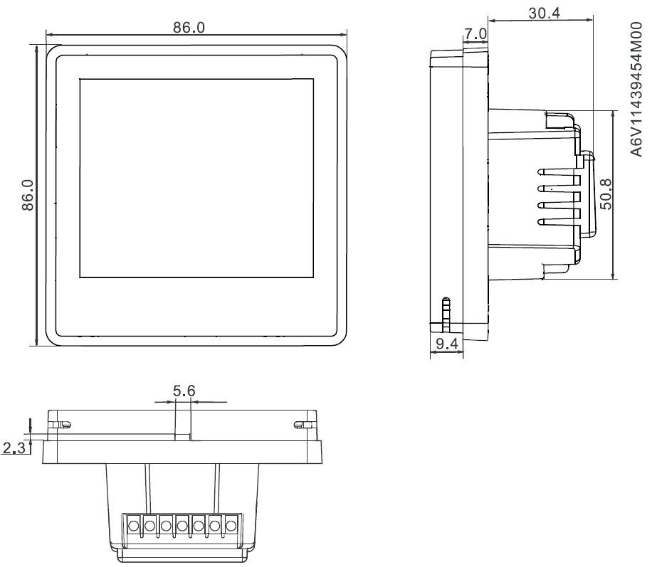
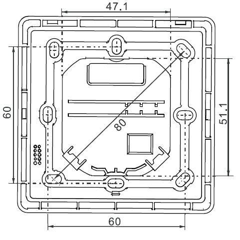
Dimensions (mm)
Issued by
Siemens Switzerland Ltd
Smart Infrastructure Global Headquarters Theilerstrasse 1a CH-6300 Zug
+41 58 724 2424
www.siemens.com/buildingtechnologies
© Siemens Switzerland Ltd, 2019 Technical specifications and availability are subject to change without notice.
Reference:
DOWNLOAD MANUALS:
Siemens RDF870KN Touch Screen Room Controller Thermostat Product Specifications Guide
![]()
Siemens RDF870KN Touch Screen Room Controller Thermostat Product Specifications Guide
Leave a Reply