
Siemens RDF660MB Flush Mount Room Thermostat

Mounting Instructions
Flush-mounted room thermostat with RS485 Modbus communications

Mounting location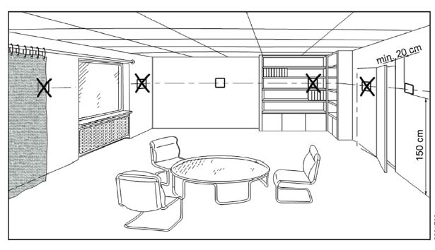
| Factory setting | |
| RDF660MB | |
| X1 | 3 = Window contact (DI) |
| X2 | 1 = External temperature sensor (AI) |
| RDF660MB/MM | |
| B1 | 9 = H/C changeover (DI) |
| S1 | 3 = Window contact (DI) |
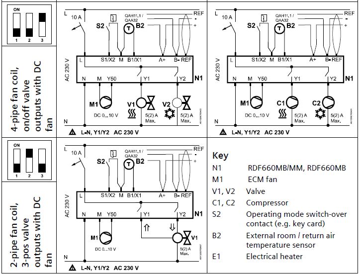
Wiring diagrams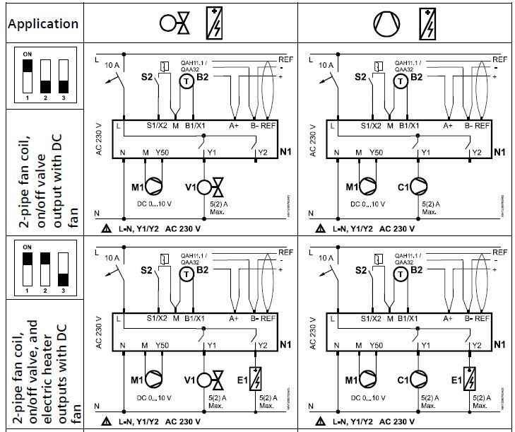
Dimensions (mm)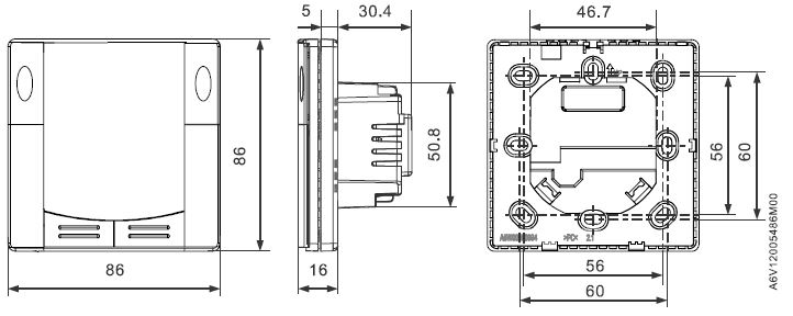
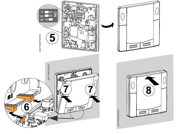
Mounting
Carefully read all wiring diagrams prior to installation to avoid damage to the device caused by incorrect wiring of high or low voltages.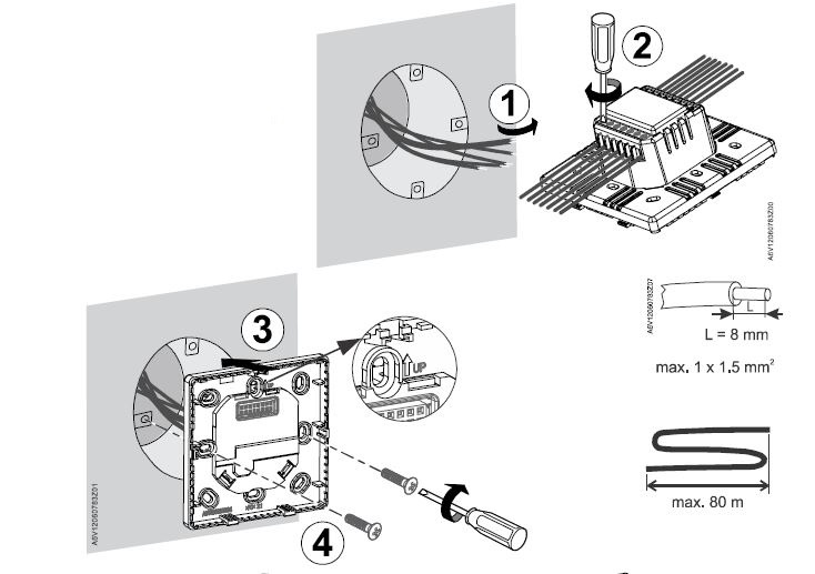
Dismounting
Operating Instructions
Needs to be configured by your HVAC installer
Needs to be enabled via parameter P02
Change room temperature setpoint
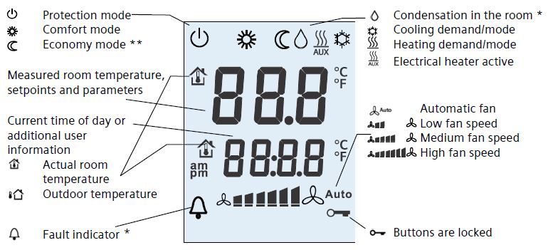
Press + or – buttons to increase or decrease the current room temperature setpoint for Comfort mode. The thermostat changes to Comfort![]() .
.
The setting range is 5…35 °C, unless limited by parameters P09 and P10.
Adjust fan speed/fan mode
Press the![]() button to adjust the fan mode and fan speed.
button to adjust the fan mode and fan speed.
In Auto mode![]() ,the thermostat automatically selects the fan speed based on setpoint and actual room temperature.
,the thermostat automatically selects the fan speed based on setpoint and actual room temperature.
In manual mode, the fan always runs at the speed that user selects:
- Low fan speed

- Medium fan speed

- High fan speed

Change thermostat operating mode
Press operating mode button![]() to change the operating mode display.
to change the operating mode display.
In Comfort mode![]() , the thermostat maintains the room temperature at the setpoint which can be readjusted using the + and – buttons.
, the thermostat maintains the room temperature at the setpoint which can be readjusted using the + and – buttons.
In Economy mode![]() , the room temperature is maintained at a lower or higher fixed setpoint (factory-set: 15 °C,
, the room temperature is maintained at a lower or higher fixed setpoint (factory-set: 15 °C, ![]() 30 °C) to save energy. Adjust parameters P11 and P12 to change the preselected setpoints. The availability of Economy mode depends on parameter P02 or via an external signal
30 °C) to save energy. Adjust parameters P11 and P12 to change the preselected setpoints. The availability of Economy mode depends on parameter P02 or via an external signal
(switch or Modbus command) such as keycard or presence detector.
In Protection mode![]() , the thermostat stops operating. However, it will operate if the room temperature is below 8 °C (heating application) against frost (P65) and the value is adjustable.
, the thermostat stops operating. However, it will operate if the room temperature is below 8 °C (heating application) against frost (P65) and the value is adjustable.
In Protection mode, press any button to activate the screen, then press the mode button to change to another operating mode.
Important: User can set Protection setpoints to OFF; the thermostat then is inactive, i.e. no protective heating or cooling function. Risk of frost!
Change from heating to cooling mode
Changeover between cooling![]() and heating
and heating![]() is either automatic using a heating/cooling changeover sensor or a remote changeover switch or via instruction from the central management station via Modbus, or manual by pressing operating mode button
is either automatic using a heating/cooling changeover sensor or a remote changeover switch or via instruction from the central management station via Modbus, or manual by pressing operating mode button![]() .
.
No changeover is possible if the thermostat is configured for cooling only or heating only (see parameter P01).
Meaning of cooling![]() and heating
and heating![]() symbols when displaying on LCD:
symbols when displaying on LCD:
- For automatic changeover or heating only/cooling only:
 Heating valve is open
 Cooling valve is open
 - For manual changeover only:
Thermostat is in heating mode
Thermostat is in cooling mode
Key lock
The key symbol![]() indicates buttons are locked. Key lock can be configured via parameter P14.
indicates buttons are locked. Key lock can be configured via parameter P14.
Reminder to clean filters and for external faults
![]() This message reminds user to clean HVAC equipment filters.
This message reminds user to clean HVAC equipment filters.
Recalibrating the sensor
After installation for at least one hour, the displayed room temperature can be recalibrated via parameter P05.
Commissioning
User can adjust several different control parameters to adapt the thermostat to your system and optimize control performance. User can do this during operation either via the buttons on the thermostat or using a commissioning tool via Modbus.
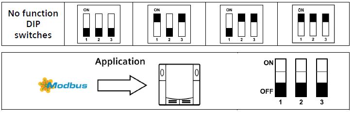
Baud rate and parity
The Baud rate can be adjusted to 9600 bps, 19200 bps (factory setting), 38400 bps or 57600 bps. The Parity can be set to none, odd or even (factory setting). Your HVAC installer can set them through additional parameters.
Important: Once making any changes on the baud rate or parity, user must reset the power before the changes take effect.
Control parameters
Proceed as follows to change the most important control parameters
- Press the – and + buttons simultaneously for more than 6 seconds.
Release, and within 2 seconds, press + again for more than 3 seconds. “P01” is displayed. - Repeatedly press the + or – button to select the required parameter.

- Press + and – simultaneously once to enter EDIT mode. Then press + or – button to change the value of the selected parameter and press + and – simultaneously to save the change.
- Repeat steps 2 to 3 to display and change additional parameters.
- Press + or – until “End” is displayed, and then press + and –simultaneously to exit parameter entry mode.
| Parameter | Description | Factory setting | Setting range |
| P01 | Control sequence | 2-pipe = 1 [selection: 0…3] 4-pipe = 4 [selection: 2, 4] | 0 = Heating only; 1 = Cooling only; 2 = H/C changeover manual 3 = H/C Changeover auto; 4 = Heating and cooling |
| P02 | Mode selection by user via operating mode button | 3 | 3 = Comfort – Protection; 4 = Comfort – Economy – Protection |
| P04 | Unit | 0 | 0 = °C (Celsius); 1 = °F (Fahrenheit) |
| P05 | Measured value correction (for built-in/external sensor) | 0 | –5 K…5 K |
| P06 | Standard display | 0 | 0 = Room temperature; 1 = Setpoint; 2 = Temperature value via bus |
| P07 | Additional display information | 0 | 0 = No display; 1 = Room temperature °C or °F; 2 = Outside temperature (via bus) 3 = Time of day (12 h) via bus; 4 = Time of day (24 h) via bus |
| P08 | Comfort basic setpoint | 21 °C | 5…40 °C |
| P09 | Minimum Comfort setpoint | 5 °C | 5…40 °C |
| P10 | Maximum Comfort setpoint | 35 °C | 5…40 °C |
| P11 | Economy heating setpoint (WheatEco) | 15 °C | OFF, 5 °C…WcoolEco |
| P12 | Economy cooling setpoint (WcoolEco) | 30 °C | OFF, WheatEco…40 °C |
| P13 *** | Electrical heater in cooling mode | 1 | 0 = Disabled; 1 = Enabled |
| P14 | Key lock | 0 | 0 = Unlock; 1 = Lock (all lock); 2 = Setpoint adjustable; 3 = Setpoint lock; 4 = Fan lock; 5 = Operating mode lock |
| All temperature settings are in increments of 0.5 °C. *** Parameter P13 is only displayed for the application “2-pipe with electric heater”. | |||
Issued by
Siemens Switzerland Ltd
Smart Infrastructure
Global Headquarters
Theilerstrasse 1a
CH-6300 Zug
Tel. +41 58 724 2424
www.siemens.com/buildingtechnologies
© Siemens Switzerland Ltd, 2020
Technical specifications and availability are subject to change without notice.
REFERENCE:
DOWNLOAD MANUALS:
Siemens RDF660MB Flush mount room thermostat Operating Instruction
OTHER MANUALS:
Siemens RDF660MB Flush mount room thermostat Product Specifications Guide
Siemens RDF660MB Flush Mount Room Thermostat Operating Instruction
Leave a Reply