
SIEMENS RDD310/MM Flush mount Room Thermostat
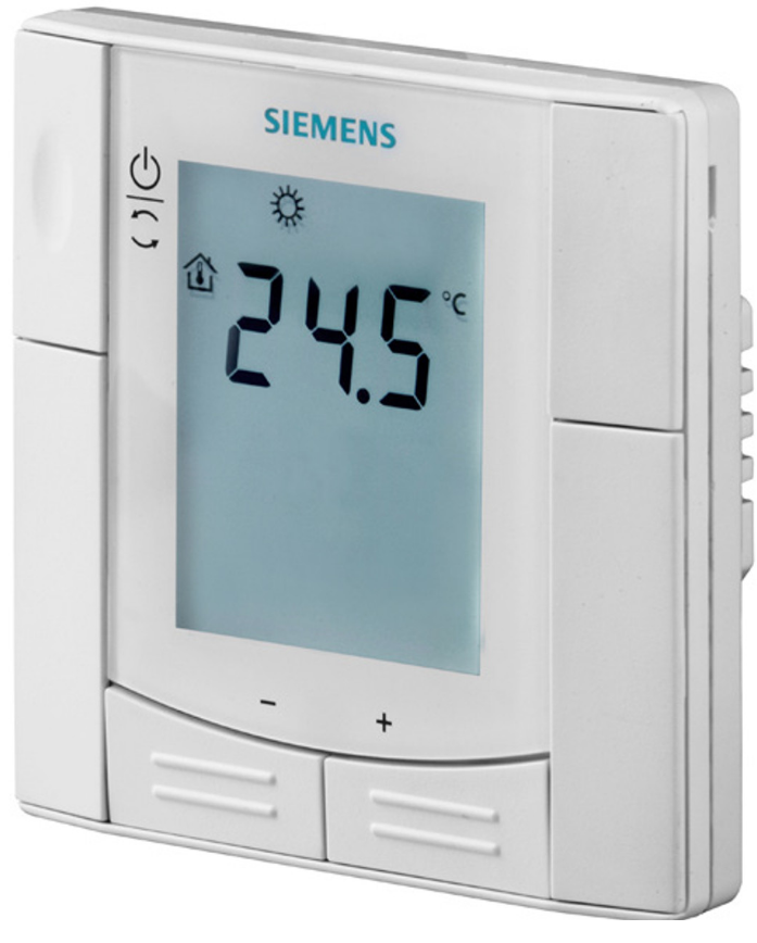
Designed for radiator and floor heating applications with either line contacts or dry contacts, and for wall-hung boiler applications with dry contacts
- Operating modes: Comfort, Protection
- Adjustable commissioning and control parameters
- Optional display of room temperature or setpoint
- Minimum and maximum setpoint limitation
- Display temperature in increments of 0.5 °C or °F
- Operating voltage AC 230 V
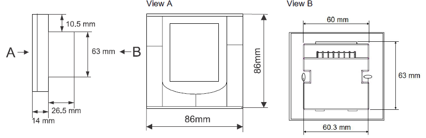
- Mounting on recessed square conduit box, fixed centers 60.3 mm
- User and parameter settings can be retained or restored with power loss
Use
Room temperature control in a heating system:
Typical applications in …
- Apartments
- Commercial buildings
- Schools
For the control of the following equipment and applications:
- Thermal valves or zone valves
- Gas or oil boilers
- Floor heating
- Radiator heating
Functions
- Selections of operating mode: comfort mode and protection mode
- Maintenance of room temperature with integrated temperature sensor
- Output for 2-position (on/off) valve actuator, SPDT (on/off) valve or 1-stage compressor
Mechanical design
The thermostat consists of two parts:
- A front panel with electronics, operating elements and a built-in room temperature sensor
- A mounting base with the power electronics
The rear side of the mounting base contains screw terminals. Slide the front panel in the mounting base and snap on. The thermostat fits on a square conduit box with 60.3 mm fixed centers.
Operating and setting elements
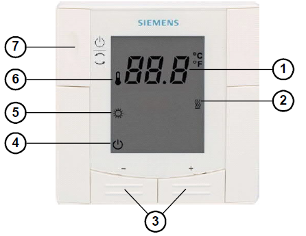
RDD310/MM User Interface
- Display of the room temperature, setpoints and control parameters
 Heating
- Buttons for adjusting the temperature setpoints and control parameters
 Protection mode
 Comfort mode
 Symbol for actual room temperature
- Button for Protection mode
 and mode selection
Type summary
Ordering
| Type | Stock Number | Designation |
| RDD310/MM | S55770-T358 | Room thermostat |
Delivery
Valve actuators should be ordered separately
Equipment combinations
On/Off actuators
| Type of units | Product number | Data Sheet | |
| Electromotoric ON/OFF valve and actuator (only available in AP, UAE, SA and IN) | 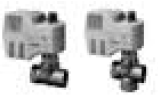 |
MVI…/MXI… | A6V11251892 |
| Electromotoric ON/OFF actuator |  |
SFA21… | N4863 |
| Thermal actuator (for radiator valve) AC 230 V, NO |  |
STA23… | N4884 |
| Thermal actuator (for radiator valves) AC 24 V, NO |  |
STA73… | N4884 |
| Thermal actuator AC 230 V (for small valves 2.5 mm) , NC |  |
STP23… | N4884 |
| Thermal actuator AC 24 V (for small valves 2.5 mm), NC |  |
STP73… | N4884 |
| Zone valve actuators (only available in AP, UAE, SA and IN) |  |
SUA… | N4832 |
| Damper actuator |  |
GDB… | N4634 |
| Damper actuator | 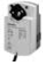 |
GSD… | N4603 |
| Damper actuator | 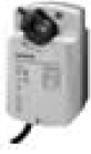 |
GQD… | N4604 |
| Rotary damper actuator | 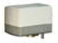 |
GXD… | N4622 |
Product Documentation
| Title | Document ID |
| Mounting Instructions | CB1M3066.1xx |
| Operating Instructions | CB1B3066.1xx |
| CE declarations | CB1T3066.1xx |
| Environmental declarations | CB1E3066en |
All the documentation can be downloaded at the following Internet address: http://siemens.com/bt/download
Security
 |
CAUTION |
| National safety regulations
Failure to comply with national safety regulations may result in personal injury and property damage.
|
Mounting
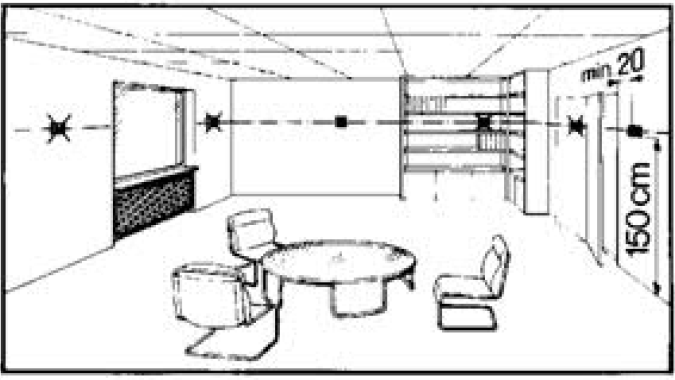
Mount the thermostat on a recessed square conduit box with fixed centers of 60.3 mm. The mounting location on a wall should not be in niches or bookshelves, not behind curtains, above or near heat sources and wind outlets or inlets, and not exposed to direct radiation. The mounting height is about 1.5 m above the floor.
Refer to the Mounting Instructions CB1M3066.1xx enclosed with the thermostat.
 |
WARNING |
| Wiring, protection and earthing must be installed in compliance with local regulations. No internal line protection for supply lines to external consumers (Q11, Q12, Q14 ). Risk of fire and injury due to short circuits!
● The AC 230 V mains supply line must have an external circuit breaker with a rated current of no more than 10 A. ● Adapt the line diameters as per local regulations to the rated value of the installed overcurrent protection device. ● Only use valves rated for AC 24…230 V. ● Disconnect from supply before opening the cover. |
Commissioning
After power up, the thermostat reset and all LCD segments flash, indicating that the reset is successful. This takes about 3 seconds. Then, the thermostat is ready for commissioning by qualified HVAC staff. The control parameters of the thermostat can be adjusted to ensure optimum performance of the entire system (see “Parameter settings”).
Calibrating the sensor
If the displayed room temperature does not match the actual temperature, you can calibrate the temperature sensor by modifying the parameter P07.
Setpoint and range limitation
For the purpose of energy saving, it is suggested to review the setpoints and setpoint ranges (parameters P03, P05 and P06). Change the setpoint to suit your individual needs.
Control sequence
Only heating sequence is available.

Control sequence
- T[°C] Room temperature
- W Room temperature setpoint
- SDH Switching differential “Heating
- Y Control output “Valve” or “Compressor
ON
The valve or compressor receives the OPEN command via control output Q14 when both of the following conditions are met.
- The acquired room temperature lies by half the switching differential below the setpoint (heating mode)
- Control output Q14 is not energized for more than the “Minimum output off time” (factory setting: 1 minute)
OFF
The valve or compressor receives the CLOSE command via control output Q14 when both of the following conditions are met.
- The acquired room temperature lies by half the switching differential above the setpoint (heating mode)
- Control output Q14 is energized for more than the “Minimum output on time” (factory setting: 1 minute)
 Control output Q11 delivers a control command which is inverted to the control command at output Q12 and which can be used for normally open valves.
Minimum output on/off time Q14 and Q12
The minimum output on/off time of Q14 and Q12 is 1 minute by default. It means that any readjustment of the setpoint will be hold for 1 minute before Q14 and Q12 react.
Parameter settings
To optimize the control performance, you can use local HMI to adjust a number of control parameters. All control parameter settings will be retained or restored with power loss. Proceed as follows to change the control parameters:
- Set the thermostat to Protection Mode .
- Press and hold down the + and – buttons simultaneously for 3 seconds.
- Release the buttons, and within 2 seconds, press and hold down the + button for 3 seconds.
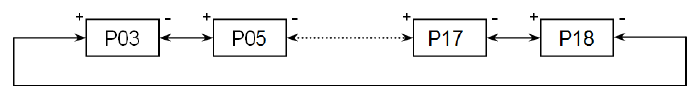
- P03 displays on the screen.
- Select the required parameter by pressing the + or – button as follows:
- Press the + and – buttons simultaneously.
- The current value of the selected parameter displays on the screen.
- Press the + or – button to change the value.
- Either press the + and – buttons simultaneously to confirm the change, or wait for 5 seconds to have the change saved automatically.
- Repeat Step 3 through 4 to change more parameters.
- 10 seconds after the last pressing, all changes are saved and the thermostat returns to protection mode.
Parameter reset
- Set the thermostat to Protection Mode .
- Press and hold down the buttons + and – simultaneously for 3 seconds.
- Release the buttons, and within 2 seconds, press the operating mode selector button twice.
- 888 displays on the screen during the reloading process.
- Release the buttons, and within 2 seconds, press the operating mode selector button
Control parameters
| Parameter | Description | Setting range | Factory setting |
| P03 | Setpoint of heating in Protection Mode | OFF, 5…40°C | 8 °C |
| P05 | Minimum setpoint limitation in Comfort Mode (WminNorm) | 5 °C…WmaxNorm | 5 °C |
| P06 | Maximum setpoint limitation in Comfort Mode (WmaxNorm) | WminNorm…40 °C | 35 °C |
| P07 | Sensor calibration | -3…3 K | 0 K |
| P08 | Switching differential heating SDH | 0.5…4 K | 1 K |
| P17 | Selection of °C or °F | °C or °F | °C |
| P18 | Display of room temperature or setpoint | OFF: Setpoint
ON: Room temperature |
ON |
Operation
Temperature control
The thermostat acquires the room temperature via its built-in sensor and maintains the setpoint by delivering 2-position valve control commands. The switching differential is 1 K in heating mode (factory setting, adjustable via parameter P08).
Display
The current room temperature or the setpoint of the current operating mode (adjustable via parameter P18) displays on the screen. Factory setting is to display the current room temperature. The heating symbol![]() displays when the heating output is active. If you want to change the unit of room temperature and setpoint between °F and °C, configure the parameter P17.
displays when the heating output is active. If you want to change the unit of room temperature and setpoint between °F and °C, configure the parameter P17.
Operating Mode
The thermostat provides both Comfort Mode and Protection Mode.
Comfort Mode![]()
In Comfort mode, press the + / – buttons to maintain the heating setpoint.
For the purpose of energy savings, the setpoint setting range has a minimum limitation (P05) and a maximum limitation (P06).
Protection Mode![]()
In Protection mode, the heating setpoint (adjustable via parameter P03) is maintained. Factory setting of heating setpoint is 8 °C.
Switching differential heating (SDH)
The temperature hysteresis range (adjustable via parameter P08) controls the activation/deactivation of heating output. Factory setting of SDH is 1 K.
Disposal
The device is considered an electronic device for disposal in accordance with the European Guidelines and may not be disposed of as domestic garbage.
![]()
- Dispose of the device through channels provided for this purpose.
- Comply with all local and currently applicable laws and regulations.
Warranty
Technical data on specific applications are valid only together with Siemens products listed under “Equipment combinations”. Siemens rejects any and all warranties in the event that third-party products are used.
Technical data
| Power supply | |
| Operating voltage | AC 230 V +10%/-15% |
| Frequency | 50/60 Hz |
| Power consumption | Max. 8 VA |
| Input relay | |
| Control input Q11 Rating | AC 24…230 V
5 mA…4(2) A |
| Output relay | |
| Control output Q14 (N.O.) / Q12 (N.C.) Rating | AC 24…230 V
5 mA…4(2) A |
| Operational data | |
| Switching differential
– Heating mode |
0.5…4 K (factory setting: 1 K) |
| Setpoint setting range
– Comfort mode – Protection mode |
5…40 °C (factory setting: 20 °C) OFF, 5…40 °C (factory setting: 8 °C)) |
| Built-in room temperature sensor
– Measuring range – Accuracy at 25 °C – Temperature calibration range |
0…49 °C <±0.5 K ±3.0 K |
| Resolution of settings and display
– Temperature setpoints – Current temperature value displayed |
0.5 °C 0.5 °C |
| Ambient Conditions and protection classification | |
| Classification as per EN 60730
– Devices of safety class – Pollution class |
II II |
| Degree of protection of housing to EN 60529 | IP30 |
| Climatic ambient conditions
– Storage as per EN 60721-3-1 – Transport as per EN 60721-3-2 – Operation as per EN 60721-3-3 |
Class 1K3 Class 2K3 Class 3K5 1) |
| Standards, directives and approvals | |
| EU conformity (CE) | CB1T3066.1xx |
| RCM conformity | A5W90002893 |
| Environmental compatibility | The product environmental declaration (CB1E3066en ) contains data on environmentally compatible product design and assessments (RoHS compliance, materials composition, packaging, environmental benefit,
disposal). |
| Housing flammability class according to UL94 | V-0 |
All the documentations can be downloaded at the following Internet address: http://siemens.com/bt/download.
No condensation is allowed
| General | |
| Connection terminals | Solid wires or prepared stranded wires:
1×0.4-1.5 mm2 |
| Weight | 0.17 kg |
| Color of front housing | White, RAL 9003 |
Diagrams
Connection terminals
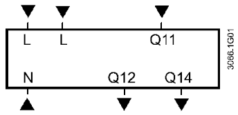
- L, N Operating voltage AC 230 V
- Q11 SPDT Relay Input (Dry Contacts) AC 24…230 V
- Q12 SPDT Relay Normal Close (NC) Output AC 24…230 V
- Q14 SPDT Relay Normal Open (NO) Output AC 24…230 V
Connection diagrams
Floor/Radiator heating AC 230 V
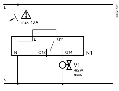
- L, N Operating voltage AC 230 V
- V1 Valve AC 230 V
Wall-hung boiler AC 230 V
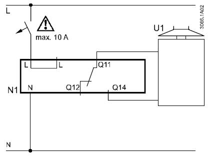
- N1 RDD310/MM
- U1 Wall-hung boiler
Floor/Radiator heating AC 24 V
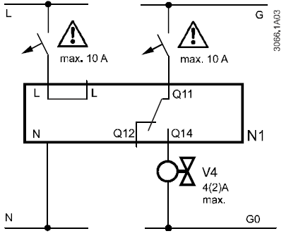
- G, Operating voltage AC 24 V G0
- V2 Valve AC 24 V
Application examples
The thermostat supports the heating applications:
- Floor heating
- Radiators
- Wall-hung boilers
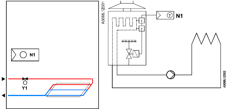
Room thermostat controls the valve of the floor heating or radiator application Room thermostat directly controls a gas-fired wallhung boiler N1 Room thermostat RDD310/MM Y1 2-port valve
Dimensions
Issued by
Siemens Switzerland Ltd Smart Infrastructure Global Headquarters Theilerstrasse 1a
- CH-6300 Zug
- Tel. +41 58 724 2424
- www.siemens.com/buildingtechnologies
© Siemens Switzerland Ltd, 2015 – 2019 Technical specifications and availability subject to change without notice
REFERENCE:
DOWNLOAD MANUALS:
SIEMENS RDD310MM Flush mount room thermostat Product Specifications Guide
![]()
SIEMENS RDD310/MM Flush Mount Room Thermostat Product Specifications Guide
Leave a Reply