Meitay-tec ETN-24-SUPER-SH Non-Programmable Thermostat

Options & Accessories
External sensor option: RS01 for remote temperature sensing (1 required) RS01 for averaging temperature with thermostat (4 required) RS02 for averaging temperature with thermostat (2 required RS02 has two thermistors in one enclosure).
- Hand held remote control.
- Door switch or window contact connection
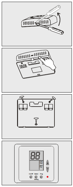
Installation Instructions
- Separate the front panel from the back panel by depressing the tongue located in the top of the unit.
- Pull the back panel out.
- Line the back panel up against the wall or flat surface. Install three screws as required.
- Make electrical connections as shown on enclosed electrical wiring connections. (Next page)
- Install the cover to the back panel; first the two tabs on the bottom and then the top tongue. Push until tight against the wall.
Wiring Connections
| C1-1S | |
| R | 24VAC |
| C | |
| S1 | |
| S2 | |
| 0 | Window Contact |
| T | |
| S3 | |
| S4 | External Sensor |
| S5 | |
| S6 | |
| S7 | Fan |
| S8 | Compressor 1 |
| C3-1S | |
| R | 24VAC |
| C | |
| S1 | |
| S2 | |
| 0 | Window Contact |
| T | |
| S3 | Compressor 3 |
| S4 | External Sensor |
| S5 | |
| S6 | Compressor 2 |
| S7 | Fan |
| S8 | Compressor 1 |
| HC12-3S | |
| R | 24VAC |
| C | |
| S1 | Heater 1 |
| S2 | Fan Medium |
| 0 | Window Contact |
| T | |
| S3 | Compressor 2 |
| S4 | External Sensor |
| S5 | |
| S6 | Fan High |
| S7 | Fan Low |
| S8 | Compressor 1 |
| C1-3S | |
| R | 24VAC |
| C | |
| S1 | |
| S2 | Fan Medium |
| 0 | Window Contact |
| T | |
| S3 | |
| S4 | External Sensor |
| S5 | |
| S6 | Fan High |
| S7 | Fan Low |
| S8 | Compressor 1 |
| HC11-1S | |
| R | 24VAC |
| C | |
| S1 | Heater 1 |
| S2 | |
| 0 | Window Contact |
| T | |
| S3 | |
| S4 | External Sensor |
| S5 | |
| S6 | |
| S7 | Fan |
| S8 | Compressor 1 |
| HC22-1S | |
| R | 24VAC |
| C | |
| S1 | Heater 1 |
| S2 | Heater 2 |
| 0 | Window Contact |
| T | |
| S3 | |
| S4 | External Sensor |
| S5 | |
| S6 | Compressor 2 |
| S7 | Fan |
| S8 | Compressor 1 |
| C2-1S | |
| R | 24VAC |
| C | |
| S1 | |
| S2 | |
| 0 | Window Contact |
| T | |
| S3 | |
| S4 | External Sensor |
| S5 | |
| S6 | Compressor 2 |
| S7 | Fan |
| S8 | Compressor 1 |
| HC11-3S | |
| R | 24VAC |
| C | |
| S1 | Heater 1 |
| S2 | Fan Medium |
| 0 | Window Contact |
| IN | |
| S3 | |
| S4 | External Sensor |
| S5 | |
| S6 | Fan High |
| S7 | Fan Low |
| S8 | Compressor 1 |
| HC23-1S | |
| R | 24VAC |
| C | |
| S1 | Heater 1 |
| S2 | Heater 2 |
| 0 | Window Contact |
| T | |
| S3 | Compressor 3 |
| S4 | External Sensor |
| S5 | |
| S6 | Compressor 2 |
| S7 | Fan |
| S8 | Compressor 1 |
| C2-3S | |
| R | 24VAC |
| C | |
| S1 | |
| S2 | Fan Medium |
| 0 | Window Contact |
| T | |
| S3 | Compressor 2 |
| S4 | External Sensor |
| S5 | |
| S6 | Fan High |
| S7 | Fan Low |
| S8 | Compressor 1 |
| HC12-1S | |
| R | 24VAC |
| C | |
| S1 | Heater 1 |
| S2 | |
| 0 | Window Contact |
| T | |
| S3 | |
| S4 | External Sensor |
| S5 | |
| S6 | Compressor 2 |
| S7 | Fan |
| S8 | Compressor 1 |
DIP switch Explanations (different configurations
Location of Dip Switches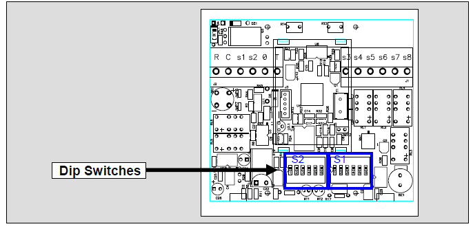
Dip Switch selection
Dip Switch S1
| Func. | Fan Speed | Time Delay* | Fan Mode in Econ. | |||
| No. | 1 Speed | 3 Speeds | 3 Minutes | No Delay | Auto Fan | Continuous |
| 1 | X | X | X | X | OFF | ON |
| 2 | OFF | ON | X | X | X | X |
| 3 | X | X | OFF | ON | X | X |
| 4 | OFF | OFF | OFF | OFF | X | X |
| 5 | X | X | X | X | X | X |
| 6 | X | X | X | X | X | X |
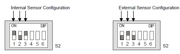
Dip Switch S2
| Func | Internal/External Sensor | Cool Only (C##) | COOL & HEAT (HC##) | Display of T. Ambient | Window Contact | |||
| No. | Internal | External | With display | No display | Stop Completely | Go to Econom. | ||
| 1 | ON | OFF | X | X | X | X | X | X |
| 2 | OFF | ON | X | X | X | X | X | X |
| 3 | ON | OFF | X | X | X | X | X | X |
| 4 | X | X | OFF | ON | X | X | X | X |
| 5 | X | X | X | X | OFF | ON | X | X |
| 6 | X | X | X | X | X | X | OFF | ON |
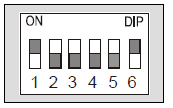
DIP Switch Operation
- The Dip Switch has 6 pins.
- Each pin can be set ON or OFF.
- In this example, pins 1,6 are ON and pins 2,3,4,5 are OFF
External sensor connection – option
| Temp
°C |
7.2 | 10.0 | 12.8 | 15.6 | 18.3 | 21.1 | 23.9 | 26.7 | 29.4 | 32.2 |
| Temp
°F |
45 | 50 | 55 | 60 | 65 | 70 | 75 | 80 | 85 | 90 |
| Res. k | 115.8 | 100.9 | 88.1 | 77.1 | 67.7 | 59.6 | 52.5 | 46.4 | 41.2 | 36.6 |
The factory default is INTERNAL SENSOR
- Disconnect the power to the thermostat (24vac).
- Move the DIP Switch S2 as described in the ‘Dip Switch S2’ table above.
- Connect the temperature sensor to S4, S5 terminals.
- Reconnect the power (24vac).
- Make sure the display reading is that of the external sensor
- The length of the cable needed for the external sensor is 100 feet (30 meters). Standard cable may be used.
- If a longer distance is needed, then the cable MUST be shielded.
- There is a wide range of sensors available for different applications, ex: ducts, rooms, etc.
- There also exists an option for averaging the temperature.
- For details please contact our technical support line or visit our web site
Operating Manual
On/Off
Press the ON/OFF button to activate or deactivate the thermostat. The word “ON” or “OFF” will appear in the display.
Set temperature
Press the SET buttons (+) or (-); the temperature will flash, change with the set buttons (+) or (-).
Selecting modes
Press the MODE button to switch between the four modes:
- Cool
- Heat
- Cool/heat (auto-change over),
- Fan only.
Selecting fan speeds
Press the FAN button to switch between speeds:
- Low
- Medium
- High
- Auto speed
Fan/Auto Fan function
- Press the FAN button to select AUTO FAN, press again to cancel. In
- AUTO FAN the fan will only run when calling for heat or cool.
Technician Settings
Set temperature limits and offset
First, set the temperature to 10°C.
Set limit for cool
- Press and hold the MODE button (5 seconds).
- “COOL” will appear on display.
- Adjust set limit for “Cool” using the “+” and “-“ buttons.
Set limit for heat
- Press the MODE button again.
- “HEAT” will appear on display.
- Adjust set limit for “Heat” using the “+” and “-“ buttons.
Set the offset (the offset is used for calibration of the measured temperature).
- Press the MODE button again.
- Adjust set offset using the “+” and “-“ buttons (range -6°C/+6°C – default 0°C).
Set limit for cool in economy mode
- Press the MODE button again.
- “AUX” and “COOL” will appear on display.
- Adjust set limit for “Cool” in economy mode using the “+” and “-“ buttons.
Set limit for heat in economy mode
- Press the MODE button again.
- “AUX” and “HEAT” will appear on display.
- Adjust set limit for “Heat” in economy mode using the “+” and “-“ buttons.
Set time delay between compressor stages
- Press the MODE button again.
- “AUX” and number will appear on display.
- Adjust set time delay between compressor stages using the “+” and “-“ buttons (Range 1-10 minutes).
Set Dead Band in Auto change over mode
- Press the MODE button again.
- “ºC” and number will appear on display.
- Adjust differential for Auto-change over mode using the “+” and “-“ buttons (Range 2ºC – 5ºC).
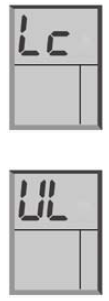
Lock/Unlock the thermostat’s buttons
- First, make sure the set temperature is NOT 10°C.
- Lock the thermostat’s buttons
- Press and hold ‘MODE’ button (5 second).
- Unlock the thermostat’s buttons
- Press and hold ‘ON’ button (5 second).
Window contact input
- The input to connect a door switch, window contact, etc. is normally open (active when closed) and Voltage Free (2 terminals).
- If window contact closes, the thermostat has two options:
- Option A: The thermostat will turn OFF.
- Option B: The thermostat will change the set point (switch to Economy Mode)
- To change these options in the thermostat please refer to the Dip Switch explanations.
REFERENCE:
DOWNLOAD MANUALS:
Meitay-tec ETN-24-SUPER-SH Non-Programmable Thermostat Operating Instructions
OTHER MANUALS:
Meitay-tec ETN-24-SUPER-SH Non-Programmable Thermostat Product Specification Guide
Meitay-tec ETN-24-SUPER-SH Non-Programmable Thermostat Operating Instructions