
Meitay-tec ETN-24-SUPER PROGRAMMABLE Thermostat

Installation
The ETN24 is designed for wall mounting in the room to be controlled. It should be located where the occupant can easily read the LCD display and use the controls. If the built in temperature sensor is being used to measure room temperature, the module should be placed where the temperature is representative of the general room conditions. Cold or warm air draughts; radiant heat and direct sunlight should be avoided.
General points to follow
- Disconnect power to the main board before installing the unit.
- The unit should not be installed on an outside wall or where there is an air draft.
- The unit must not be exposed to direct sunlight.
- The standard height to install this unit is 1.5 meter (5 feet) from the floor.
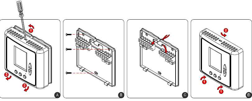
Installation procedure
- Separate the front panel from back panel by pressing the tongue located in the top of the unit and pull the back panel out.
- Line the back panel up against the wall or flat surface. Install three screws as required.
- Make electrical connections as shown on enclosed electrical wiring diagram.
- Install the cover to the back panel; first the two tabs on the bottom and then the top tongue.
- Push until tight against the wall.
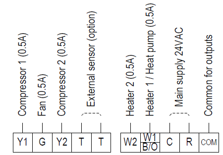
Wiring
Before connecting or disconnecting any wires, ensure that all power supplies have been switched off and all wires are potential-free to prevent equipment damage and avoid electrical shock. Do not run wiring close to transformers or high-frequency generating equipment. Complete and verify all wiring connections before applying power to the controller to which the module is connected
Meitay-tec
- Tel: +972-3-9626462
- Fax: +972-3-9626620
- www.meitavtec.com
- [email protected]
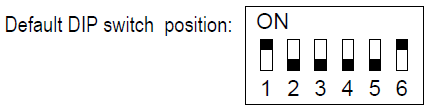
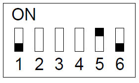
DIP Switch and Jumpers Configuration
The DIP Switch is located on the top of the back side of the thermostat (above the connectors).
| Switch | Internal/External Sensor | HP | HC | Time delay for compressor | ||||
| Internal sensor | External sensor | Heat Pump in heat “B” | Heat Pump in cool “O” | Oil/Gas heat | Electric heat | No delay | 3 Minutes | |
| 1 | ON* | OFF | X | X | X | X | X | X |
| 2 | X | X | ON | OFF* | X | X | ||
| 3 | X | X | ON | OFF | ON | OFF* | X | X |
| 4 | X | X | X | X | X | X | ON | OFF* |
| 5 | OFF* | ON | X | X | X | X | X | X |
| 6 | ON* | OFF | X | X | X | X | X | X |
For complete reset of the unit, use JMP1 (3 pins) as follows: move the jumper from “A” position to “B” position, wait 30 seconds and move the jumper back to “A” position. JMP2 (2 pins) is not in use and must always stay shorted.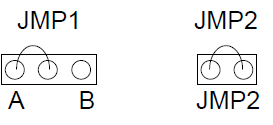
External sensor Connection (option)

Connecting the external sensor
- Disconnect power to the thermostat.
- Move switch 5 to ON position and switches 1 and 6 to OFF position.
- Connect the temperature sensor to the T-T terminals.
- Reconnect power to the thermostat.
Notes:
- The wire length for the external sensor can be up to 100 feet (30 meters) with standard cable.
- If the distance is greater than 30 meters (100 feet) the wire MUST be shielded
Operating instructions
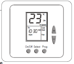
On/Off
- Press the [On/Off] button to turn the thermostat ON.
- Press and hold the [On/Off] button (10 sec.) to turn the thermostat OFF.
Set point
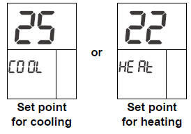
In Cool mode and in Heat mode:
- Press the [+] or [-] buttons – “COOL” or “HEAT” will appear on display and the set-point temperature for cooling or heating will flash.
- Adjust the set-point temperature for cooling or heating using the [+] or [-] buttons.
- Wait until display returns to normal
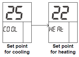
In Fan only mode or in auto change-over mode (2 set-points):
- Press the [+] or [-] buttons – “COOL” will appear on display and the set-point temperature for cooling will flash.
- Adjust the set-point temperature for cooling using the [+] or [-] buttons.
- Wait 3 seconds – “HEAT” will appear on display and the set-point temperature for heating will flash.
- Adjust the set-point temperature for heating using the [+] or [-] buttons.
- Note the the set-point for heating must be lower than the set-point for cooling.
- Wait until display returns to normal
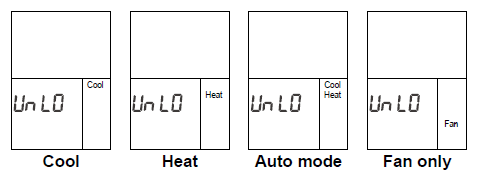
Modes / Auto fan
- Press the [Select] button once to enter Modes selection
- Use the [+] and [-] buttons to switch between modes:
- “Cool”…………………Cooling
- “Heat”…………………Heating
- “Cool” & “Heat”………Auto mode
- “Fan”…………………. Fan only
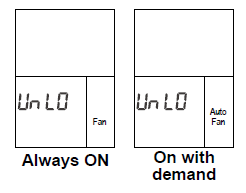
- Press the [Select] button again to enter Auto fan selection
- Use the [+] and [-] buttons to switch between:
- “Fan”…………….……Fan is on continuously
- “Auto Fan”……………*Fan cycles on with demand
- Auto Fan is not available in “Fan only” mode.
- In Heat mode, with Oil/Gas heat configuration (i.e., furnace):
- Auto Fan – The fan will never be activated.
- Fan – The Fan will work continuously.
- Press the [Select] button again to return to normal display
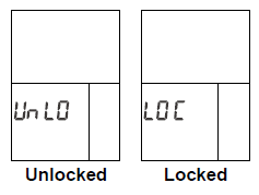
Lock Buttons
Use the Lock option to prevent users from making unwanted changes. When the thermostat is locked, the [Select], [+] and [-] buttons are disabled, however, the users can turn the thermostat ON or OFF. The display will alternate between “Loc” and real time clock.
- Make sure both temperature set points are different than 10°C.
- Lock the thermostat – Press and hold the [Select] button (20 seconds) until “Loc” appears on display.
- Unlock the thermostat – Press and hold the [Select] button again (20 seconds) until “UnLo” appears on display
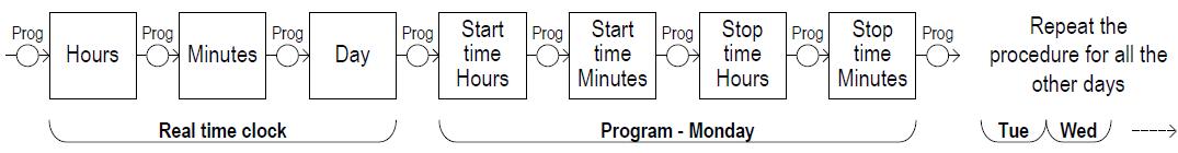
Weekly Program
The thermostat is 7-DAY PROGRAMMABLE. It can be programmed with up to 7 different programs, 1 for each day, with start time and stop time
Enable/Disable/Override the weekly program
- Press & Hold the [Prog] button (20 sec.) to enable/disable the program.
- When enabled, the words “Start” or “Stop” will appear on display.
- To exit programming mode, press the [On/Off] button until normal display is reached or wait 30 seconds.
Note that the words “Start” or “Stop” on display will indicate the current status of the weekly program as follows: Override the program (After hours timer): The word “Stop” will flash when the occupant manually turned the unit ON, during stop event. Override period is 2 hours before turning the unit back OFF.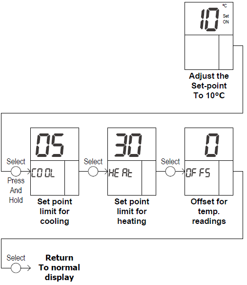
Technician Settings
- Adjust the set point temperature to 10°C. Wait until display stops flashing.
- Press and hold the [Select] button (5 sec.) to enter technician settings.
- Use the [Select] button to switch between different configurable parameters.
- Use the [+] and [-] buttons to make adjustments or switch between options
Set point temperature limit for cooling
Indication: “Cool” and the set point Temperature limit for cooling. Range: 5…30°C, default 5°C.
Set point temperature limit for heating
Indication: “Heat” and the set point temperature limit for heating. Range: 5…30°C, default 30°C.
Offset for calibration of the measured temperature
- Indication: “Offs” and a number between (-6) and (+6).
- Range: -6…+6°C, default 0°C.
Meitay-tec
- Tel: +972-3-9626462
- Fax: +972-3-9626620
- www.meitavtec.com
- [email protected]
REFERENCE:
DOWNLOAD MANUALS:
Meitay-tec ETN-24-SUPER PROGRAMMABLE Thermostat Installation Guide
OTHER MANUALS:
Meitay-tec ETN-24-SUPER PROGRAMMABLE Thermostat Product Specification Guide
Meitay-tec ETN-24-SUPER PROGRAMMABLE Thermostat Installation Guide
Leave a Reply