Neptronic TROB24 Programmable Thermostat
Features
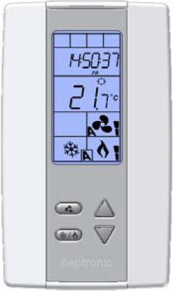
- Attractive modern look with a large LCD and backlight
- Icons-driven information and 1 line of text information
- 2 Pipes Analog, ON/OFF or Floating or
- Pipes Analog, ON/OFF with local re-heat function
- Auto fan and ON/OFF function enable or disable
- 7 days of programming logic
- 2 or 4 daily independent time schedules and temperature
- AM-PM or 24-hour time display
- Temporary override pr program temperature
- Selectable internal or external temperature sensor
- Changeover by contact or external temperature sensor
- Celsius or Fahrenheit scale selectable
- Anti-freez protection
| Technical Data | TFC24F3XYZ3 |
| Inputs | 1 Analog input (external temperature sensor 10Kohms) |
| 1 Analog input (change over 10Kohms or dry contact) | |
|
Outputs |
1 Fan analog or 3 Fan speed dry contracts 24Vac, 1A max 3A in-rush |
| 2 Analog outputs (cooling and/or heating 0-10Vdc) | |
| 1 Analog output (local reheat 0-10Vdc ) | |
| 2 Triacs output (cooling and/or heating) 24Vac, 0.3A max fused / triac | |
| 1 Triacs output (local reheat) 24Vac, 0.3A max fused / triac | |
| Power supply | 22 to 26 Vac 50/60Hz |
| Power consumption | 1 VA max |
| Set point range | 10ºC to 40ºC [50ºF to 104ºF] |
| Control accuracy | Temperature: ±0.4ºC [0.8ºF] |
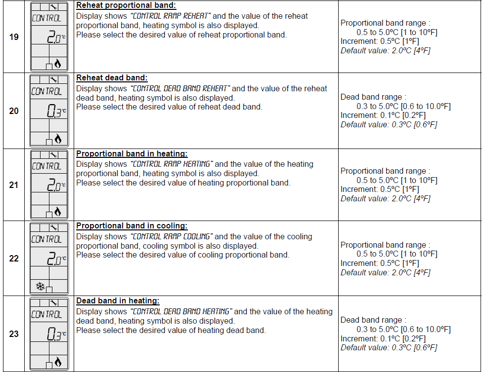
| Proportional band | 0.5ºC to 5ºC [1ºF to 10ºF] adjustable (heat/cool/reheat independent) |
| Dead band | 0.3ºC to 5ºC [0.6ºF to 10ºF] adjustable (heat/cool/reheat independent) |
| Electrical connection | 0.8 mm2 [18 AWG] minimum |
| Operating temperature | 0ºC to 50ºC [32ºF to 122ºF] |
| Storage temperature | -30ºC to 50ºC [-22ºF to 122ºF] |
| Relative Humidity | 5 to 95 % non condensing |
| Degree of protection of housing | IP 30 (EN 60529) |
| Weight | 160 g. [0.36 lb] |
Presentation
Dimensions
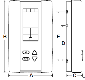
| Dimension | Inches | Metric (mm) |
| A | 2.85 | 73 |
| B | 4.85 | 123 |
| C | 1.00 | 24 |
| D | 2.36 | 60 |
| E | 3.27 | 83 |
Mounting Instructions
CAUTION: Risk of malfunction. Remove power prior to separating the thermostat cover from its base.
- Remove the screw (captive) holding the base and the front cover of the thermostat.
- Lift the front cover of the thermostat to separate it from the base.
- Pull the wire through the base hole.
- Secure the base to the wall using wall anchors and screws (supplied). Make the appropriate connections.
- Mount the control module on the base and secure using the screw.
Terminal Description
| 2 Pipe | Analog | On/Off | Floating | ||||||||||||
| Terminals | Fan option | analog | 1 spd | 2 spd | 3 spd | analog | 1 spd | 2 spd | 3 spd | analog | 1 spd | 2 spd | 3 spd | ||
|
TB1 |
1 | Common | Common | Common | Common | ||||||||||
| 2 | 24 Vac | 24 Vac | 24 Vac | 24 Vac | |||||||||||
| 3 | Common Triac | Common Triac | Common Triac | Common Triac | |||||||||||
| 4 | Triac output 1 (TO1) | Floating output 1 | – | 2 Pipe on/off | 2 Pipe floating (close) | ||||||||||
| 5 | Triac output 2 (TO2) | – | – | 2 Pipe floating (open) | |||||||||||
| 6 | Triac output 3 (TO3) Reheat | Local reheat (optional) (on/off or pulse) | Local reheat (optional) (on/off or pulse) | Local reheat (optional) (on/off or pulse) | |||||||||||
| 7 | Common Relay | – | Common Relay | – | Common Relay | – | Common Relay | ||||||||
| 8 | Digital output 1 (DO1) | – | – | – | High | – | – | – | High | – | – | – | High | ||
| 9 | Digital output 2 (DO2) | – | – | High | Med | – | – | High | Med | – | – | High | Med | ||
| 10 | Digital output 3 (DO3) / Analog Fan Speed (AO4) | Fan analog | 1 spd | Low | Low | Fan analog | 1 spd | Low | Low | Fan analog | 1 spd | Low | Low | ||
| 11 | Not used | – | – | – | |||||||||||
| 12 | External Temp. Sensor (AI1) | External Temp. Sensor (optional) | External Temp. Sensor (optional) | External Temp. Sensor (optional) | |||||||||||
| 13 | External Changeover (AI2) | External Changeover | External Changeover | External Changeover | |||||||||||
| 14 | Analog output 1 (AO1) | 2 Pipe analog | – | – | |||||||||||
| 15 | Analog output 2 (AO2) | – | – | – | |||||||||||
| 16 | Analog output 3 (AO3) Reheat | Local reheat analog (optional) | Local reheat analog (optional) | Local reheat analog (optional) | |||||||||||
| 4 Pipe | Cool & Heat Analog | Cool & Heat On/Off | Cool Analog-Heat On/Off or pulse | Cool On/Off – Heat Analog | |||||||||||||||
| Terminals | Fan option | analog | 1 spd | 2 spd | 3 spd | analog | 1 spd | 2 spd | 3 spd | analog | 1 spd | 2 spd | 3 spd | analog | 1 spd | 2 spd | 3 spd | ||
|
TB1 |
1 | Common | Common | Common | Common | Common | |||||||||||||
| 2 | 24 Vac | 24 Vac | 24 Vac | 24 Vac | 24 Vac | ||||||||||||||
| 3 | Common Triac | Common Triac | Common Triac | Common Triac | Common Triac | ||||||||||||||
| 4 | Triac output 1 (TO1) | Floating output 1 | – | 4 Pipe on/off cool | – | 4 Pipe on/off cool | |||||||||||||
| 5 | Triac output 2 (TO2) | – | 4 Pipe (on/off or pulse) heat | 4 Pipe (on/off or pulse) heat | – | ||||||||||||||
| 6 | Triac output 3 (TO3) Reheat | Local reheat (optional) (on/off or pulse) | Local reheat (optional) (on/off or pulse) | Local reheat (optional) (on/off or pulse) | Local reheat (optional) (on/off or pulse) | ||||||||||||||
| 7 | Common Relay | – | Common Relay | – | Common Relay | – | Common Relay | – | Common Relay | ||||||||||
| 8 | Digital output 1 (DO1) | – | – | – | High | – | – | – | High | – | – | – | High | – | – | – | High | ||
| 9 | Digital output 2 (DO2) | – | – | High | Med | – | – | High | Med | – | – | High | Med | – | – | High | Med | ||
| 10 | Digital output 3 (DO3) / Analog Fan Speed (AO4) | Fan analog | 1 spd | Low | Low | Fan analog | 1 spd | Low | Low | Fan analog | 1 spd | Low | Low | Fan analog | 1 spd | Low | Low | ||
| 11 | Not used | – | – | – | – | ||||||||||||||
| 12 | Ext. Temp Sensor (AI1) | External Temp. Sensor (optional) | External Temp. Sensor (optional) | External Temp. Sensor (optional) | External Temp. Sensor (optional) | ||||||||||||||
| 13 | External Changeover (AI2) | – | – | – | – | ||||||||||||||
| 14 | Analog output 1 (AO1) | 4 Pipe analog cool | – | 4 Pipe analog cool | – | ||||||||||||||
| 15 | Analog output 2 (AO2) | 4 Pipe analog heat | – | – | 4 Pipe analog heat | ||||||||||||||
| 16 | Analog output 3 (AO3) Reheat | Local reheat analog (optional) | Local reheat analog (optional) | Local reheat analog (optional) | Local reheat analog (optional) | ||||||||||||||
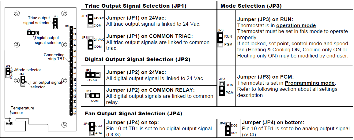
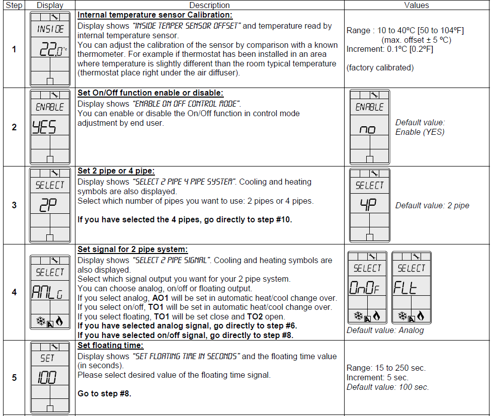
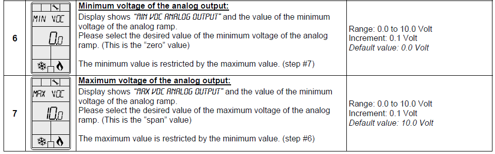
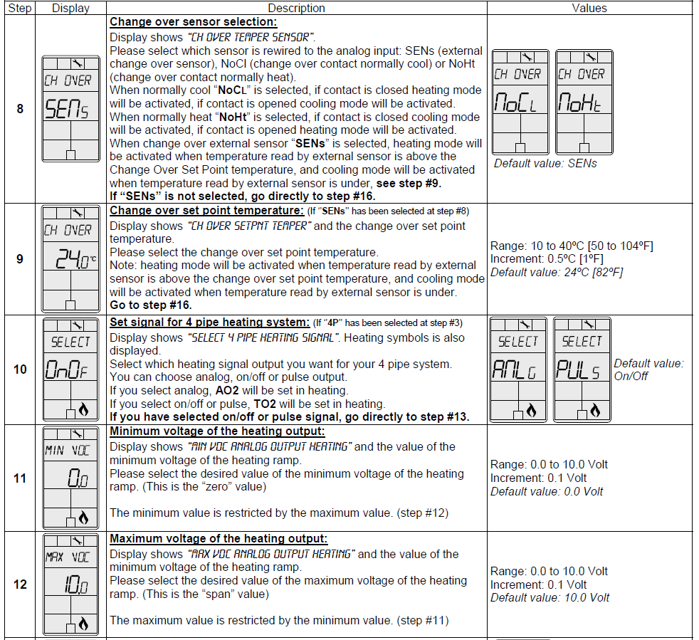
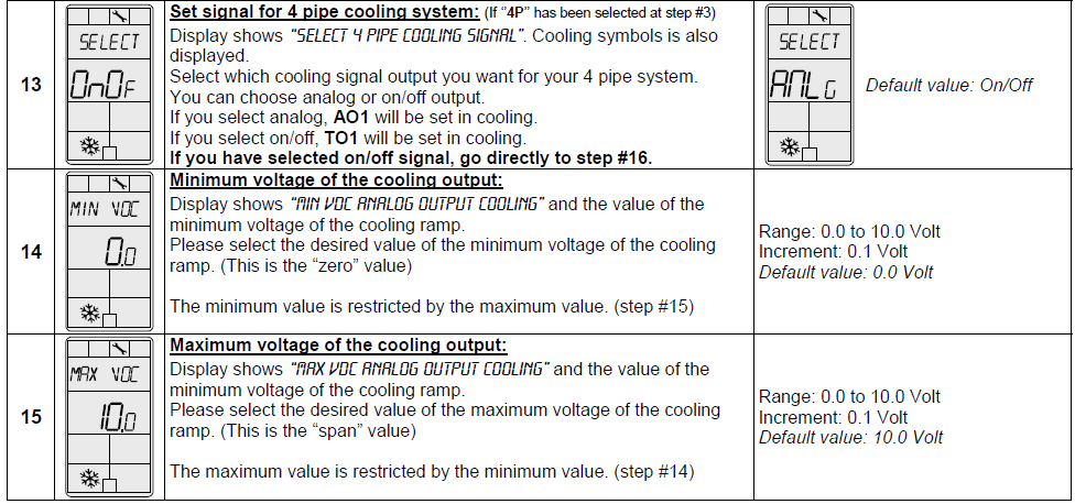
Settings on PC Board
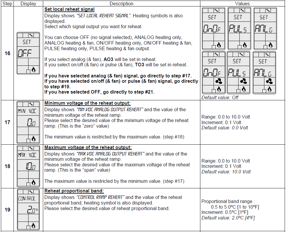
Programming Mode
When in this mode this symbol ![]() is displayed. Please press the button
is displayed. Please press the button ![]() to advance to the next program function, press the button
to advance to the next program function, press the button![]() to return to the preceding stage, and press the button
to return to the preceding stage, and press the button![]() to
to![]() change the value. You can leave the programming mode at any time, changed values will be recorded.
change the value. You can leave the programming mode at any time, changed values will be recorded.
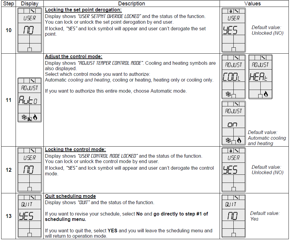
 Scheduling Mode (Available when in Operation Mode; JP3 set on RUN)
Push the button![]() for 5 seconds to access the user schedule menu. When in this mode, this symbol
for 5 seconds to access the user schedule menu. When in this mode, this symbol![]() is displayed. Press on the button
is displayed. Press on the button  to advance to the following program function, press on the button
![]() to return to the previous step, and press on the
to return to the previous step, and press on the ![]() or
or ![]() button to change the value. The system will exit the menus and return to normal function if you navigate through the entire menu or if no button is pressed for 5 minutes, changed values will be saved.
button to change the value. The system will exit the menus and return to normal function if you navigate through the entire menu or if no button is pressed for 5 minutes, changed values will be saved.
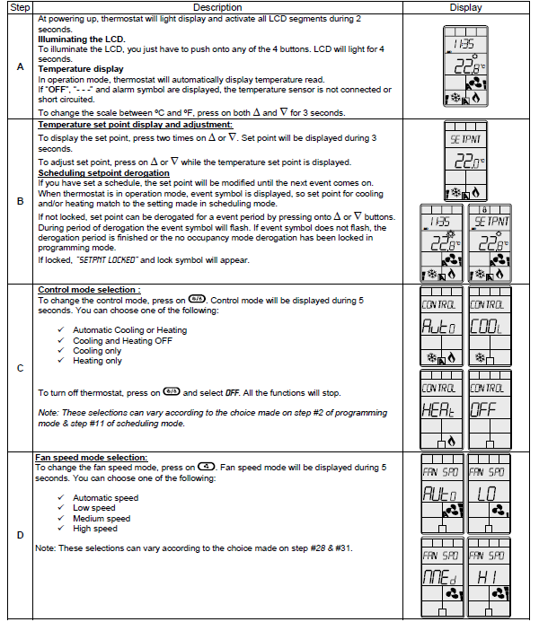
Operation Mode
Recycling at end of life
At end of its life, please return the thermostat to your Neptronic® local distributor for recycling. If you need to find the nearest Neptronic® authorized distributor, please consult www.neptronic.com.
REFERENCE:
DOWNLOAD MANUALS:
Neptronic TROB24 Programmable Thermostat Product Specifications Guide
![]()
Neptronic TROB24 Programmable Thermostat Product Specifications Guide