
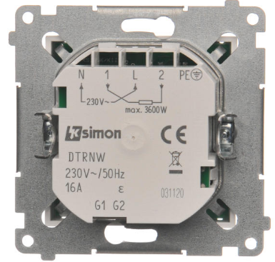
Kontakt-Simon DTRNW.01-11 Digital thermostat
Product Marking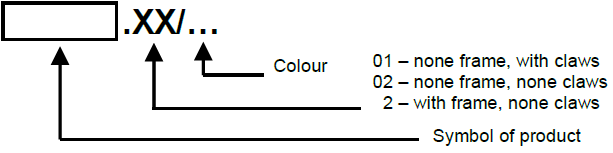
TECHNICAL DATA
- Voltage 230V AC (+10% / -20%) / 50Hz
- Load current 10A 2300W 2-pole with outer sensor (DTRNSWZ…)
- 16A 3600W 1-pole with outer sensor (DTRNSZ…)
- 16A 3600W 1-pole (DTRNW…)
- Temperature regulation range 5 ÷ 40°C
- Antifreeze Protection programmable (default +5°C)
- Type of operation automatic
- Method regulation ON-OFF
- Type of sensor inner (air) – all types outer (floor) (sensor MGF47k), length: 3m
- Night Setback programmable (default reduced by 5°C in 7 hours)
- Weight 94g (128g with sensor)
- Height of installation 1.0 ÷ 1,5 m
- Protection class IP20
- Reference standards PN-EN 60730-1
APPLICATION
- The Temperature Regulator with Night Setback and Special Floor Protection Function is designed to control underfloor heating systems, electric heaters, etc. in a manner assuring maintenance of constant temperature.
- Total power of the connected load may not exceed 2300W (DTRNSWZ…) or 3600 (DTRNSZ…, DTRNW…)
- Load of higher power shall be connected through an additional contactor.
- The Temperature Regulator 10A 2-pole (DTRNSWZ…) switch guarantees complete disconnection of the load circuit from the network.
- The Temperature Regulator automatically detects if an external temperature sensor is connected.
- If an external floor-or air sensor is connected, the internal temperature sensor is automatically set out of service.
- The Temperature Regulator can be mounted by use of screws in flush-mounted Ø60mm installing boxes and surface boxes and in multiple-box set Simon54 Premium.
INSTALLATION RECOMMENDATIONS
The regulator should be installed on a wall 1,0 ÷ 1,5 m above the floor level, in a heated room in a place assuring free air circulation (see the figure ‘Method of Installation’). It should not be exposed to direct influence of other sources of heat (e.g. the sun), to draughts (close to windows, doors etc.) or water. Attention should be paid to correct connection of power supply, i.e. a phase conductor to L terminal and a neutral conductor to N terminal. A terminal for connection of a protection conductor enables maintenance of protection circuit continuity. Temperature Regulator is stablied about 30 min., after connect of power supply.
STARTING UP
| ON/OFF. On /Off-button Even in OFF position, while in Thermostat Modus Antifreeze Temperature Function, is still active. |
Thermostat / Regulator Modus
Choose forth and back between Thermostat and Regulator: button 3 sec. NOTE: whatever switching on Regulator Modus adjust A parameter to value: 10%. The interval for control of Regulator: P7 parameter Button: increase the temperature (Thermostat) increase A parameter(1÷99%) (Regulator) Button: lower the temperature (Thermostat) lower A parameter (1÷99%) (Regulator) The desired temperature shows up for 5 sec. before returning to display the actual temperature [°C] (Thermostat) or value [%] (Regulator). Regulator Modus in use is seen in pic.1. |
| Night Setback in Thermostat Modus only Press button If Green Light, the Night Setback is activated. quick push-on button |
|
| Antifreeze
When Thermostat Modus is chosen, and the Thermostat being turned OFF, and the Display shows FS (Freezing Security), the Thermostat Antifreeze Function will however connect the “Heating Elements” controlled by the Thermostat. In case temperature measures below P2 parameter, the Thermostat turn on the Heating Elements preventing frost damages.
NOTE! In Regulator Modus, the Antifreeze Function will not be activated when the Thermostat being turned OFF. |
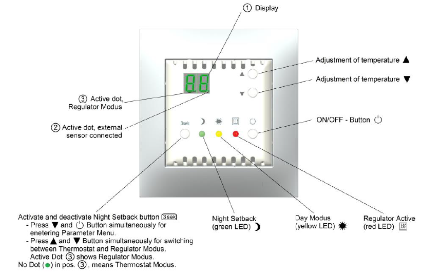
Explanation of Display Information
· Display ① shows continually the actual temperature at the moment · By pressing the · Dot ② in the display indicates floor or wall sensor is connected · Dot ③ indicates that the Thermostat is in regulator Modus · Red LED · Yellow LED · Green LED Lowering the temperature with set value (i.e. 5°C), and 50% in Regulator Modus |
| Child Safety
Press the ON/OFF button for 8 seconds to activate the Child Safety, and the display acknowledge by short flashing. For cancelling this function, repeat the same procedure. |
Calibration (Menu P0)
Place a reliable thermometer close to the Thermostat and adjust the Thermostat by using automatically by saved after 10 seconds. |
| Maximum Limit for wooden floor
Contact the supplier of the floor material for further information about the maximum temperature. Set this recommended temperature in Menu P6. |
Pic. 1. Example Uout in Regulator Modus: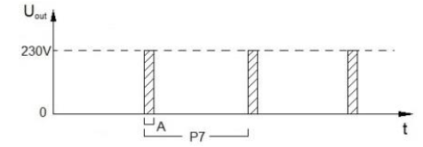 |
 , cancels the Night Setback for this day but returns automatically to Night Setback again next day. For permanent canceling, enter into parameter P3.
 button quickly, the set temperature shows up
DIAGRAM OF TEMPERATURE REGULATOR CONNECTION TO THE ELECTRICAL SYSTEM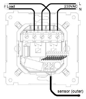
METHOD OF INSTALLATION
Caution: Disconnect the power supply before installing the temperature regulator. Installation should be carried out by a person with suitable qualifications.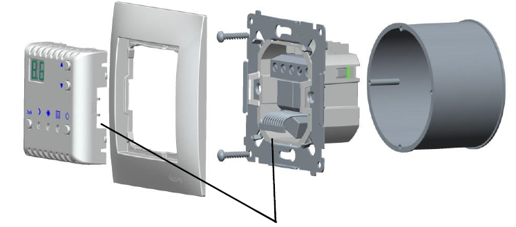
Caution: The wires should be connected to the terminals before the plate closes.
PARAMETER SETTINGS
| How to enter the menu | Press the Button and Minus-button for 5 sec. until shows up in the display |
| Maneuvering between the parameters | Push the Button |
| Editing parameters | Push or – button for setting new values |
| Save new settings | Being automatically saved after 10 sec. |
| Return to Factory Settings | Push and hold buttons simultaneously for a minimum of 3 sec. |
| Menu | Parameter | Settings | Fact. Setting |
| P0 | Calibrating temperature | Adjustable +/-5°C in according to the “master” thermometer | 0 °C |
| P1 | Antifreeze | 1 = On / 0= Off | 1 |
| P2 | Set Antifreeze Temp. | 1÷20 °C (only valid in Thermostat Modus) | 5 °C |
| P3 | Night Setback | 1 = On / 0= Cancel Night Setback | 1 |
| P4 | Hours in Night
Setback |
1÷23 | 7 hours |
| P5 | Lowering temp. in
Setback |
1÷20 °C (In Thermostat Modus and 50% in Reg.
Modus) |
5 °C |
| P6 | Max. Floor Temp | 5÷40 °C | 28 °C |
| P7 | Interval for control of temp/regulating | 1÷20 min. | 15 min. |
| P8 | Maximum Limit | 1 = On / 0 = Off / 2 = air *) | 1 |
| PA | Floor Variants | 00=47k, 01=12k, 02=15k, 03=10k, | 00=47k |
| Pb | Display Brightness | 0÷50 (0 means bright and 50 means dark) | 20 |
Reference
Download manual:
Kontakt-Simon DTRNW.01-11 Digital thermostat User Manual
Leave a Reply