JUNG FTR LS 231 WW Floor Thermostat
Safety instructions
Electrical devices may only be mounted and connected by electrically skilled persons.
Serious injuries, fire, or property damage are possible. Please read and follow the manual fully.
The danger of electric shock. Always disconnect before carrying out work on the device or load. In so doing, take all the circuit breakers into account, which support dangerous voltages to the device and or load.
The danger of electric shock. The sensor cable is connected to the mains voltage potential. If the sensor cable is damaged, immediately disconnect the device from the mains by switching off all associated circuit breakers.
This manual is an integral part of the product and must remain with the end customer.
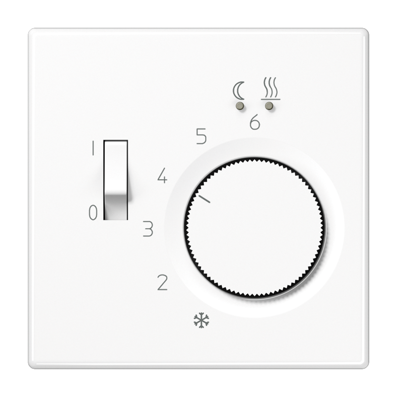
Device components

- Room temperature controller insert
- Frame
- Status LED
- Central plate
- Control knob
- Adjustment rings for temperature limit
Intended use
- Electronic temperature controller for controlling electric underfloor heating or floor temperature conditioning systems
- Control of the floor temperature in closed rooms
- Mounting in appliance box with dimensions according to DIN 49073
Product characteristics
- Manually setting a comfort temperature for the floor
- Manually switching off the temperature control
- Input terminal for activation of reduction temperature (ECO) via central clock
- External temperature sensor (remote sensor)
- Frost protection function
- Controller output working method: pulse width modulation (PWM) or two-point switchable
- Interruption of heating for 5 minutes after one hour in continuous heating mode
- Permanent LED operation possible
Functional description
ECO operation
In many areas of the building, it makes sense for the temperature to be set to a lower ECO temperature at certain times rather than to heat permanently to the comfort temperature. By connecting the input terminal Ø to 230 V, the temperature is reduced by 4 °C and the status LED lights up green. This should be controlled by a central clock.
Controller adaptation
Depending on the heating system, the control behavior can be adjusted.
- Pulse width modulated control (factory setting): The output is not permanently actuated, but for a time period (pulse width) that depends on the difference between the target and actual temperature. This method brings the actual temperature gradually closer to the target temperature.
- Two-point control: The output remains switched on until the selected target temperature has been exceeded by 0.5 °C. The output will not be switched on again until the target value is undercut by 0.5 °C. Since most heating systems respond very slowly, this type of control can entail temperature overshooting.
Operation
Brief overview
| Function | Control knob | Status LED * | LED colour |
| Change room tem- perature | … turn right or left | maximum 2 minutes | Red = heating mode
green = ECO heating mode Orange = frost protection (10 seconds) |
| Display operating mode | … press briefly | 10 seconds. | Red = heating mode
green = ECO heating mode Orange = frost protection |
* In permanent operation, the status LED lights up continuously during the active heating phase, but with reduced brightness.
Increasing or reducing the floor temperature
- Turn the control knob to the right or left.
If the setpoint temperature is not reached, the LED lights up for a maximum of 2 minutes in the color of the current operating mode. The indication can also take place during the entire heating process (see Activating/deactivating permanent LED operation).
In the middle position, the device regulates to approx. 30 °C target temperature.
The lowest target temperature is approx. 5 °C and the highest target temperature is approx. 50 °C
Indication of the current operating mode
- Press the control knob briefly.
The LED lights up for 10 seconds in the color of the current operating mode.
Orange = frost protection, red = heating mode, and green = ECO heating mode.
Switching off the temperature control
- Press the control knob for longer than 2 seconds until the LED lights up orange.
The device has switched to frost protection. The frost protection prevents the temperature from falling below 5 °C.
Each time the control knob is turned, the LED lights up orange for 10 seconds. - To activate the temperature control, press the control knob again for more than two seconds.
The device switches back to heating mode. The LED lights up red for 10 seconds.
Activating/deactivating permanent LED operation
In permanent operation, the status LED lights up continuously during the active heating phase.
- Press the control knob for longer than 10 seconds until the LED lights up or flashes in the color magenta.
LED lights up magenta = permanent operation is active
LED flashes magenta = permanent operation is inactive (default setting) - Press the control knob briefly to switch the mode.
- Press the control knob for more than one second to adopt the displayed mode.
After 10 seconds without actuation, the displayed mode is automatically adopted.
Information for electrically skilled persons
Remote sensor mounting instructions
The remote sensor must meet the requirements of protection class II and be routed together with sensor cable S03VV in a protective tube. This protects the remote sensor from humidity and allows for an easier exchange in the event of a repair.
If the status LED (3) flashes red rapidly, there is an error at the remote sensor. No temperature measurement, and thus no control, is possible.
If the sensor cable is interrupted or no remote sensor is connected, continuous heating is carried out. If there is a short circuit of the sensor cable, heating is not carried out.
DANGER!
Mortal danger of electric shock.
Disconnect the device. Cover up live parts.
Connecting and fitting the device
Recommended installation height: 1.50 m.

- External temperature sensor (remote sensor)
- Switching contact of the central clock
- Electric underfloor heating
- Connect insert (1) according to the connection diagram (see figure 2). Observe the conductor cross-sections (see figure 3).
- Optionally, connect the ECO operation input Ø via a switching contact of a central clock (8).
If 230 V is applied to the input, the target temperature is reduced by 4 °C. - Fit the device in the appliance box; terminals must be at the bottom.
- Fit the frame, central plate, and control knob.
- Switch on the mains voltage.
Commissioning
Setting control behavior
Factory setting: pulse width modulated control (PWM)
This setting can be used with most heating systems without adaptation.
Changing the settings
- Press the control knob for longer than 20 seconds.
The LED flashes green for PWM control and green/blue for 2-point control. - Press the control knob briefly: The control behavior is changed.
- Press the control knob for longer than one second.
The current control behavior is saved and the setting mode is exited automatically.
After approx. 2 minutes without any operation, the menu is exited without saving.
Setting the temperature limits
The temperature control has a setting range from 5 to 50 °C. The adjustment rings in the central plate can be used to limit the temperature setting range.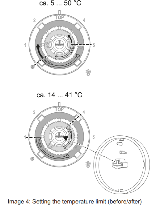
- Pull the control knob off the central plate so that the adjustment rings are visible Bild.
Pulling off is done by hand or with a suitable tool, e.g. vacuum lifting tool or keycap puller. - Turn the large blue adjustment ring clockwise to the desired minimum temperature.
Each notch corresponds to a change of about 2 °C. - Turn the small red adjustment ring anticlockwise to the desired maximum temperature.
The respective adjustment ring can only be turned in one direction. To return to the original setting, continue turning to the respective position. - Replace the control knob, observing the coding (Fig. 4, bottom) of the control knob and rotary axle.
Technical data
- Rated voltage AC 220 … 240 V ~
- Mains frequency 50 / 60 Hz
- Switching current 10 A
- Connected load
- Ohmic load 2300 W
- Standby power max. 0.15 W
- Ambient temperature -5 … +45 °C
- Storage/transport temperature -25 … +70 °C
- Cable length inputs max. 100 m
- Controller class (EU 811/2013) IV
- Contribution to energy efficiency 2%
- FFNTC remote sensor
- Dimensions Ø×H 7.8 × 28 mm
- Length connecting cable 4 m (can be extended to 50 m)
- Degree of protection IP 67
Remote sensor resistance values
| Temperature
(°C) |
Resistance
(kΩ) |
Temperature
(°C) |
Resistance
(kΩ) |
|
| 5 | 89.5 | 30 | 26.2 | |
| 10 | 68.8 | 35 | 20.9 | |
| 15 | 53.5 | 40 | 16.7 | |
| 20 | 41.9 | 45 | 13.5 | |
| 25 | 33.0 | 50 | 11.0 |
The resistance values can only be measured if the sensor is disconnected.
Warranty
The warranty is provided in accordance with statutory requirements via the specialist trade.
ALBRECHT JUNG GMBH & CO. KG
Volmestraße 1
58579 Schalksmühle
GERMANY
Telefon: +49 2355 806-0
Telefax: +49 2355 806-204
[email protected]
www.jung.de
Floor thermostat
Reference
Download manual:
JUNG FTR LS 231 WW Floor thermostat Operating Instruction
![]()