Peco TW205-206 WIRELESS THERMOSTAT

Introduction
THE PECO WAVE WIRELESS SYSTEM™
The PECO Wave Wireless System is comprised of the TW205 or TW206 wireless thermostat paired with a RW205 receiver. Optional accessories to the system are the SW205 wireless occupancy sensor and SW206 wireless door switch. The TW205 thermostat is a nonprogrammable digital thermostat that may be powered by battery, 24 VAC, or both. It features separate heating and cooling setpoints, auto changeover, fan control functions, and wireless communication with the RW205 receiver. The RW205 receiver is wired to the HVAC equipment and controls all outputs. The optional SW205 occupancy sensor and SW206 door switch also communicate wirelessly with the RW205 receiver to signal occupancy status. The TW206 thermostat is a programmable model. It includes all the features of the TW205 thermostat plus 7-day programming, four time periods per day, and hold/override options.
APPLICATIONS AND FEATURES
- The PECO Wave Wireless System is intended for use in PTAC, PTHP, and On/Off control applications.
- System mode selections: Off-Heat-Cool-Auto-Setback
- Stages: 1 Heat/1 Cool, 2 Heat/1 Cool, 1 Heat/2 Cool
- 6 outputs (RW205): 1 Heat, 1 Cool, Up to 3 Fan, Outside Air Damper / Reversing Valve
- Fan control: 1-3 Speeds, Cycling (Auto) or Continuous (On)
- Permanent memory: The thermostat does not need batteries to store user-configured settings in memory. Nonvolatile memory (EEPROM) saves temperature setpoints, fan, and system settings for an unlimited time. In the event of power loss, time settings are kept for at least one year (TW206).
- Connections for Remote Temperature Probe and Setback (RW205
FRONT PANEL REFERENCE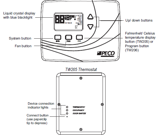
WARNING
- READ THESE INSTRUCTIONS CAREFULLY BEFORE ATTEMPTING TO INSTALL, OPERATE OR SERVICE THIS THERMOSTAT.
- Failure to observe safety information and comply with instructions could result in PERSONAL INJURY, DEATH AND/OR PROPERTY DAMAGE.
- To avoid electrical shock or damage to equipment, disconnect power before installing or servicing and use only wiring with insulation rated for full thermostat operating voltage.
- Before installing this control, the Voltage Selection Switch must be placed in the correct position. See instructions.
- To avoid potential fire and/or explosion do not use it in potentially flammable or explosive atmospheres.
- Retain these instructions for future reference. This product, when installed, will be part of an engineered system whose specifications and performance characteristics are not designed or controlled by PECO. You must review your application and national and local codes to assure that your installation will be functional and safe.
SPECIFICATIONS
- Temperature Range: 50° to 90°F (10° to 32°C)
- Differential: 1°F (0.5°C)
- Input Power: TW205 / TW206 thermostat: Two AA alkaline
- Input Power (cont.): batteries or 24 VAC, 50/60 Hz
- RW205 receiver: 24 VAC or 100-277 VAC, 50/60 Hz
- Wireless Type: 902 to 928 MHz Band, FHSS
- (Frequency Hopping Spread Spectrum)
- Wireless Range: 100 ft minimum in the open air
- Operating Temperature: 0° to 120°F (-17° to 48°C)
- Shipping Temperature: -20° to 130°F (-28° to 54°C)
- Operating Humidity: 5% to 95% RH, non-condensing
- Physical Dimensions: TW205 / TW206: 4.5”H x 5.75”W x 1.1”D
- RW205: 4.8”H x 3.8”W x 1.3”D
WAVE WIRELESS SYSTEM MOUNTING CONSIDERATIONS
When selecting mounting locations for Wave Wireless System components, it is important to consider the number and types of obstructions between components. The Wave Wireless System will communicate through walls and other obstructions but they will reduce the effective operating range of these devices. Mounting any device within a metal enclosure may significantly reduce its communicating range. The Wave Wireless System uses Frequency Hopping technology to improve its resistance to wireless interference; however, malfunctioning or improperly used wireless devices may interfere with the Wave Wireless System. Take note of any other wireless devices in use near the Wave Wireless System before installation or if communication errors occur frequently.
INSTALLATION
STEP 1 OF 4: THERMOSTAT WIRING AND MOUNTING
Mounting Location
The thermostat should be used indoors only. It should be mounted on an inner wall in a location with freely circulating air, and where it will be responsive to changes in room temperature. Avoid mounting near heat-generating appliances (i.e. TV, heater, refrigerator), or in direct sunlight.
Power Options
The thermostat will operate on either 24 VAC power or two AA alkaline batteries. Follow instructions for chosen power option in the appropriate section below. If desired, thermostat may operate on 24 VAC power with battery backup (follow the 24 VAC Power instructions
24 VAC Power – Wiring and Mounting Instructions
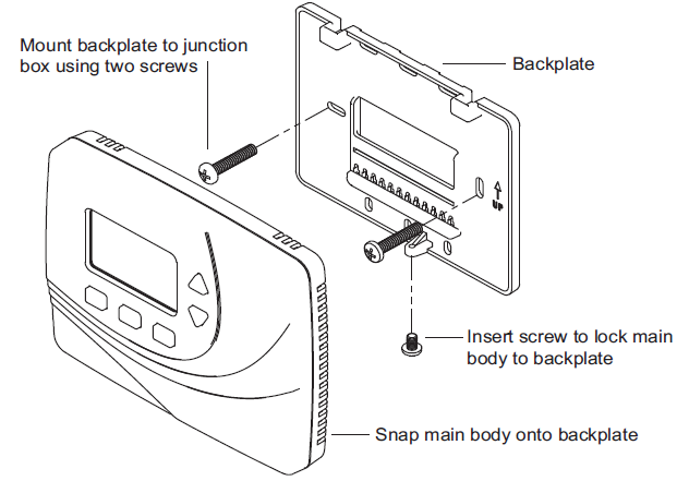
This thermostat mounts on a standard 4” x 4” device box with a 2” x 4” horizontal mud ring. See Figure 1.
- To avoid electrical shock or damage to equipment, disconnect all power before installing this thermostat.
- Remove old thermostat (if applicable):
- Remove the front cover of old thermostat. With wires still attached, remove backplate from the wall. If the old thermostat has a wall mounting plate, remove the thermostat and the wall mounting plate as an assembly.
- Before removing wires from old thermostat, label each wire with the terminal designation from which it was attached.
- Disconnect the wires from the old thermostat one at a time. Do not let wires fall back into the wall.
- Mount TW205/TW206 thermostat backplate:
- Pull wires through the hole of the TW205/TW206 backplate.
- Attach the thermostat backplate to the wall using the enclosed mounting screws. Tighten screws evenly but do not over-tighten.
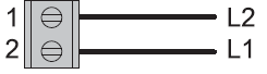
- Attach wires to the TW205/TW206 thermostat backplate:
- Loosen the screws on the terminal block to allow the wires to be inserted easily.
- Ensure the insulation on each wire is stripped to the proper length, and insert them into the terminal block as shown in the wiring diagram:
- Tighten each terminal block screw until the wires are held firmly in place. Ensure no uninsulated wire is exposed.
- If batteries are to be used for backup, install the batteries into the compartment in the back of the thermostat.
- Attach the thermostat to the backplate and install the optional retaining screw provided with the mounting hardware.
Battery Power Only – Mounting Instructions
- If powered by batteries only, the TW205/TW206 thermostat may be mounted at any location.
- In this case, a device box is not required.
- Mount thermostat backplate to the wall using the enclosed mounting screws. Tighten screws evenly but do not over-tighten.
- Install the batteries into the compartment in the back of the thermostat.
- Attach the thermostat to the backplate and install the optional retaining screw provided with the mounting hardware.
STEP 2 OF 4: THERMOSTAT CONFIGURATION / SERVICE MENU
The installer must configure the thermostat matches the installed heating/cooling system. The Service Menu allows the installer to modify configuration variables that are not normally accessed by the end user. The configuration variables are identified by Menu Number, as listed in the “Service Menu Functions” table.
- Simultaneously press the ▲ ▼ buttons, and hold down for 5 seconds. This takes you to the Service Menu and menu item number “1” will be shown.
- Push the SYS button to scroll to the Service Menu item number to be configured. The item number that is shown is the one you are selecting.
- Push the ▲ ▼ buttons to configure the selected menu item.
- To save your configuration selection and go to the next Menu Number, press SYS.
Saving and Exiting the Service Menu
The Service Menu exits and returns to the user display after 15 seconds of inactivity. Changed values are automatically saved to permanent memory.
STEP 3 OF 4: WIRELESS CONNECTION TO RW205 RECEIVER
- Install the RW205 receiver, following the procedure in the “RW205 Receiver Installation and Operating Instructions” document that came with the RW205.
- After both the TW205/TW206 thermostat and RW205 receiver are installed, turn on power to the equipment.
- NOTE: If you are installing more than one TW205 and RW205 set nearby each other, you must only apply power to one set at a time then perform the connection process. This will prevent unintentional pairing of devices. After the connection process is performed the TW205 thermostat can remain on.
- On the thermostat: Go to Service Menu #43 and select “ON”. After 15 seconds, the display will show “99” and begin counting down to 0. This countdown indicates thermostat is now waiting for a connection request from the RW205 receiver.
- On the RW205 receiver: Depress the CONNECT button using the tip of a paperclip. (The CONNECT button is the small hole on the front of the receiver, immediately under the three device lights. It is not labeled.)
- During the connection process, if any light on the RW205 stops fl ashing, this means a device has been found and successfully paired with. The RW205 will attempt to connect to any available device for 2 minutes or until all available devices have been paired
STEP 4 OF 4: CHECK THERMOSTAT OPERATION
- After thermostat and receiver installation, confi guration, and wireless connection are complete, check thermostat operation:
- Set fan to ON. The blower should begin to operate.
- Set the System Switch to AUTO, or available selection. Using the ▲ button, adjust temperature above the room temperature to cycle heating stage(s) on. Using the ▼ button, adjust temperature below the room temperature to cycle cooling stage(s) on.
INTERPRETING THE RW205 INDICATOR LIGHTS
After devices have been paired (wirelessly) to the RW205 the corresponding Indicator Lights should remain lit. If communication is broken for more than 5 minutes, in the case of the TW205/206, or 30 minutes for the SW205/206, the Indicator Light associated with that device will shut off. In the event of a communication loss with the TW205/206, RW205 will shut off all outputs. If the RW205 loses communication with the SW205 or SW206, it will assume the room is occupied. The indicator lights on the RW205 can also be used to diagnose communication problems. If the RW205 receives valid messages from a connected device, it will blink once. If the RW205 receives invalid messages, it will blink twice. An invalid message could be caused by an excessive amount of obstruction between the RW205 and paired devices, or a large amount of interference from other wireless devices. If the RW205 indicates invalid messages frequently, review the “Mounting Considerations” section of this guide for more information.
| MENU | FEATURE | RANGE | STD.MODEL DEFAULT | DESCRIPTION / COMMENTS |
| 1 | F / C | 0, 1 | 1 | Sets the temperature display in Fahrenheit (1) or Celsius (0). |
| 3 | Fan Delay | 0-99 Sec | 0 | The amount of time (in seconds) the lowest available fan speed will run after the thermostat outputs are disabled. |
| 4 | Range Low | 50-90°F, 10-32°C | 50°F | The lowest selectable temperature setpoint value. |
| 5 | Range High | 50-90°F, 10-32°C | 90°F | The highest selectable temperature setpoint value. |
| 6 | Setback Low | 50-82°F, 10-28°C | 55°F | The temperature setpoint value you want the thermostat to Heat to when the thermostat is in the Setback mode. 0 represents OFF. |
| 7 | Setback High | 50-90°F, 10-32°C | 90°F | The temperature setpoint value you want the thermostat to Cool to when the thermostat is in the Setback mode. 0 represents OFF. |
| 8 | Zone Temp Offset | +/- 9°F,
+/- 4.5°C |
0°F | Zone Temperature offset adjusts the sensed Zone Temperature reading from the A to D converter, allowing calibration in the field. |
| 9 | Keypad Lockout | 0-2 | 0 | Allows you to choose what the occupant can access. The Service Menu is still available if Keypad Lockout is ON.
1= Disables all buttons except ▲ and ▼ buttons. 2= Disables all buttons. 0= No keypad lockout. |
| 10 | Fan Program Mode | 1-3 | 3 | 1= ON= Fan is always on regardless of demand.
2= AUTO= Fan is only on with heating or cooling demand. 3= ON or AUTO= User can choose either selection. |
| 11 | Fan Program Speed | 1-3 | 3 | 1= HIGH= 1-speed fan (only displays “On Auto” in Fan menu) 2= LOW, HIGH= 2-speed fan
3= LOW, MED, HIGH= 3-speed fan |
| 12 | System Program Mode | 0-3 | 1 | Allows you to determine what system modes the occupant can select. 0= OFF, AUTO
1= OFF, HEAT, COOL, AUTO 2= OFF, HEAT, COOL 3= AUTO, HEAT, COOL |
| 14 | Setback Mode Enable | 0, 1 | 0 | When ON (1), Setback is shown as an available system mode selection. If Setback mode is selected, the thermostat will control to the current Setback Heat and Setback Cool setpoints. 0= OFF
1= ON |
| 15 | Outside Air Damper | 0, 1 | 0 | 1= OFF= Cycles; OA output cycles with active heat or cool demand.
0= ON= Continuous; OA output is active anytime the thermostat is out of the OFF mode. |
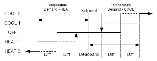
| 17 | Minimum Deadband Adjust | 3-10°F,
1.5-5°C |
3°F | A changeover deadband value prevents short cycling between Heating and Cooling modes. The value is adjustable to meet various HVAC system requirements. |
| 25 | Pre-occupancy Purge | 0-3 Hours | 0 Hours | Defines a period of time for the fan to run prior to an occupied area, to circulate fresh air. |
| 30 | Cycles Per Hour for Cool | 0-6 CPH | 5 CPH | 0 disables cycling and thermostat becomes an ON/OFF control. |
| 32 | Cycles Per Hour for Heat | 0-12 CPH | 3 CPH | 0 disables cycling and thermostat becomes an ON/OFF control. |
| 35 | Heat Recovery Rate | 0-18°F/Hr, 0-10°C/Hr | 5°F/Hr, 3°C/Hr | 0 disables ramp recovery, uses step response |
| 36 | Cool Recovery Rate | 0-18°F/Hr, 0-10°C/Hr | 5°F/Hr, 3°C/Hr | 0 disables ramp recovery, uses step response |
| 40 | Output Min Off Time for Heat and Cool | 1-10 Minutes | 4 Minutes | Sets the minimum off time for both heat and cool output. |
| 41 | OA/ RV Output Configuration | 0-4 | 0 | 0= OA/ RV Output is used to control the outside air damper. 1= OA/ RV Output is on when there is a demand for heating. 2= OA/ RV Output is on when there is a demand for cooling. 3= OA/ RV Output is 2nd Stage Heat.
4= OA/ RV Output is 2nd Stage Cool. |
| 42 | Temp Source (Remote) | 0, 1 | 0 | 0= The temperature will be measured by the thermostat’s internal sensor.
1= The temperature will be measured by a remote probe connected to the RW205 receiver. |
| 43 | Pairing Start | 0, 1 | 0 | This item should remain OFF until the installer is ready to perform the wireless connection process to the RW205 receiver.
0= OFF= The thermostat will not attempt to pair with the RW205 receiver. 1= ON= The thermostat will attempt to pair with the RW205 receiver. |
| 45 | Intermittent Fan | 0, 1 | 0 | If enable is selected, the lowest speed fan will operate during setback operation. 0= Disable
1= Enable |
| 46 | Intermittent Fan On Time | 1-60 Minutes | 5 Minutes | Defines the duration in which low-speed fan will be on. Fan On Time will be activated after Fan Off Time has passed. |
| 47 | Intermittent Fan Off Time | 1-60 Minutes | 25 Minutes | Defines the duration in which fan will be off. Fan Off Time will be activated after Fan On Time has passed. |
APPLICATION NOTES
Single-Stage Systems
Systems that use dedicated 1 HEAT and 1 COOL and do not require secondary or staged outputs:
- On the RW205 receiver:
- Connect the HEAT OUTPUT to the heating valve.
- Connect the COOL OUTPUT to the cooling valve.
- On the thermostat:
- Set Service Menu #41 to “0”.
- (In this case the OA/RV OUTPUT can be used to control and outside air damper.)
Multi-Stage Systems
- On the RW205 receiver:
- Connect the HEAT OUTPUT to the primary heating input on the system.
- Connect the COOL OUTPUT to the primary cooling input on the system.
- Connect the OA/RV OUTPUT to the secondary heating input on the system.
- On the thermostat:
- Set Service Menu #41 to “3”.
Systems that use 1 HEAT and 2 COOL:
- On the RW205 receiver:
- Connect the HEAT OUTPUT to the primary heating input on the system.
- Connect the COOL OUTPUT to the primary cooling input on the system.
- Connect the OA/RV OUTPUT to the secondary cooling input on the system.
- On the thermostat:
- Set Service Menu #41 to “4”
- Set Service Menu #41 to “4”
Heat Pump Systems
Systems that use a dedicated Compressor input and do not have separate heating and cooling inputs:
- On the RW205 receiver:
- Connect the HEAT OUTPUT to the COOL OUTPUT and connect both outputs to the Compressor input on the system.
- Connect the OA/RV OUTPUT to the reversing valve on the system.
- On the thermostat:
- If the reversing valve needs to be energized with a demand for heating, set Service Menu #41 to “1”.
- If the reversing valve needs to be energized with a demand for cooling, set Service Menu #41 to “2”.
Systems that use a dedicated Heat and Cool and internally assesses the compressor demand inside the system:
- On the RW205 receiver:
- Connect the HEAT OUTPUT to the primary heating input on the system.
- Connect the COOL OUTPUT to the primary cooling input on the system.
- Connect the OA/RV OUTPUT to the secondary heating input on the system.
- On the thermostat:
- If the reversing valve needs to be energized with a demand for heating, set Service Menu #41 to “1”.
- If the reversing valve needs to be energized with a demand for cooling, set Service Menu #41 to “2”.
Fan Coil Systems
The RW205 receiver has no pipe sensor, therefore seasonal changeover cannot be controlled. The Wave Wireless System will operate fan coil systems using the dedicated HEAT OUTPUT and COOL OUTPUT connected to the associated valve on the fan coil system. For fan coil systems using 2 HEAT or 2 COOL that are not changed seasonally, refer to the Multi-Stage Systems section.
Setback
The RW205 receiver’s SETBACK INPUT is a low level switchable input that is normally open. When the switch is closed, the system is in setback mode. In setback mode, the heating and cooling setback limits are used as temperature control points and fan operation is cycled with demand at the lowest speed. Pressing any button on the TW205/206 thermostat will override the setback for 1 hour. Setback function is enabled via the Service Menu on the thermostat:
- To enable setback function: Set Service Menu #14 to “1”.
- To specify the Heating setback limit: Access Service Menu #6 and scroll to desired temperature.
- To specify the Cooling setback limit: Access Service Menu #7 and scroll to the desired temperature.
USER OPERATION (TW205 ONLY)
The following operating instructions are only for the TW205 nonprogrammable thermostat. Please refer to the “TW206 Owner’s Manual” for the operating instructions for the TW206 programmable thermostat
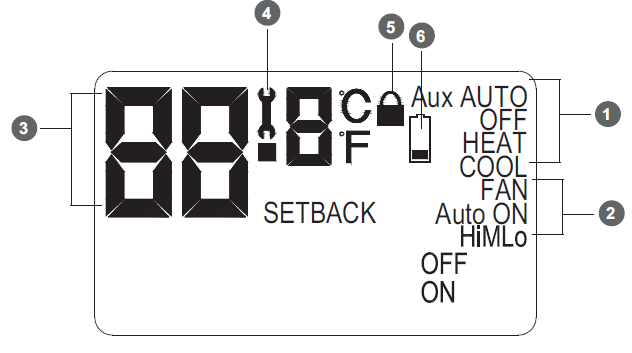
TW205 Display Reference
- System Mode Indicators. Displays whether the system is in heat, cool, auto, setback, or off. See the “System Button Operation” section for information.
- Fan Operation Indicators. See the “Fan Button Operation” section for information.
- Temperature Display. The current room temperature is shown during normal display.
- Service Indicator. The wrench symbol is displayed when there is a temperature sensor error.
- It indicates there is an open or a short connection to the sensor.
- When this occurs, the thermostat will disable all outputs and illuminate the wrench symbol.
- A service technician should be called to determine the cause of the error.
- Keypad Lockout Indicator.
- Low Battery Indicator.
Saving Changes
As you navigate your thermostat, be aware of the thermostat’s save and exit protocol:
- The thermostat automatically saves all the changes you make, as you make them.
- When you are in the SYSTEM or FAN menus:
- If you push a button that is not applicable to the current menu, all changes are saved and the thermostat goes to the menu associated with the button that was pushed.
- If the thermostat is idle for fi ve seconds, the thermostat times out, saves all changes, and returns to the thermostat’s normal display.
▲ or ▼ Button Operation
- The thermostat displays the current room temperature. Press ▲ to increase, or ▼ to decrease, the desired room temperature (setpoint).
Pressing SYS will light up the system mode options described below (if enabled by your thermostat’s installer in the Service Menu). Press SYS to scroll through the options. As you scroll, the current option will be flashing. To select the flashing option, wait for the five second timeout, which saves your option and returns you to the default display.
MENU DESCRIPTION
- HEAT The thermostat operates as a Heating only thermostat.
- COOL The thermostat operates as a Cooling only thermostat.
- AUTO The thermostat automatically selects the appropriate Heat or Cool mode depending upon the setpoint (desired temperature) and zone temperature (actual temperature). OFF Turns the system off by disabling all outputs on the RW205 Setback mode is an energy saving feature that minimizes the heating and cooling when the room is not occupied. Setback mode overrides the standard setpoints by telling the thermostat to instead use the setback setpoints for heating and cooling. The setback setpoint temperatures are factory default or installer-selected during installation. During setback mode, when a demand for heating or cooling exists, the fan will run at the lowest speed.
- Automatic setback mode: The TW205 thermostat can be used with PECO SW205/206 wireless occupancy detection devices. Setback mode is automatically controlled by those devices. For more information, see the “SW205/206 Installation and Operating Instructions”.
- Manual setback mode: Select SETBACK in the SYSTEM menu. Setback temperature settings will remain in effect until you manually turn off setback mode. Selecting HEAT, COOL, or AUTO in the SYSTEM menu will turn off setback and resume user-selected settings
Pressing FAN will light up the fan mode options described below (if enabled by your thermostat’s installer in the Service Menu). Press FAN to scroll through the options. As you scroll, the current option will be fl ashing. To select the fl ashing option, wait for the fi ve-second timeout, which saves your option and returns you to the thermostat’s default display.
MENU DESCRIPTION
- ON Hi High speed fan is on continuously, even if no demand for heating or cooling exists.
- ON M Medium speed fan is on continuously, even if no demand for heating or cooling exists.
- ON Lo Low speed fan is on continuously, even if no demand for heating or cooling exists.
- AUTO Hi High speed fan cycles with active demand for heating and cooling.
- AUTO M Medium speed fan cycles with active demand for heating and cooling.
- AUTO Lo Low speed fan cycles with active demand for heating and cooling.
F/C Button Operation
- Pressing the F/C button toggles the temperature display between Fahrenheit and Celsius.
- Pressing the F/C button does not change the stored value in the Service Menu.
FCC
This device complies with part 15 of the FCC rules. Operation is subject to the following two conditions:
- this device may not cause harmful interference, and
- this device must accept any interference received, including interference that may cause undesired operation.
Warning: Modifications not expressly approved by the manufacturer could void the user’s authority to operate the equipment under FCC rules. NOTE: This equipment has been tested and found to comply with the limits for a Class A digital device, pursuant to part 15 of the FCC Rules. These limits are designed to provide reasonable protection against harmful interference in a residential installation. This equipment generates, uses and can radiate radio frequency energy and, if not installed and used in accordance with the instructions, may cause harmful interference to radio communications. However, there is no guarantee that interference will not occur in a particular installation. If this equipment does cause harmful interference to radio or television reception, which can be determined by turning the equipment off and on, the user is encouraged to try to correct the interference by one or more of the following measures:
- Reorient or relocate the receiving antenna.
- Increase the separation between the equipment and receiver.
- Connect the equipment into an outlet on a circuit different from that to which the receiver is connected.
- Consult the dealer or an experienced radio/TV technician for help.
REFERENCE
DOWNLOAD MANUAL
Peco TW205-206 WIRELESS THERMOSTAT INSTALLATION INSTRUCTIONS
![]()
Peco TW205-206 WIRELESS THERMOSTAT INSTALLATION INSTRUCTIONS