
Peco T4522-001 Programmable Thermostat
SET CLOCK, YEAR, MONTH, DAY
- Press ▲/ ▼ to select 12 or 24 HR mode, then press Next.
- Press ▲/ ▼to select clock hour, then press Next.
- Press ▲/▼to select clock minutes, then press Next.
- Press ▲/ ▼ to select clock year, then press Next.
- Press ▲/ ▼ to select the current month, then press Next. Note: Mo (month) appears.
- Press ▲/ ▼to select the current date.
Note: Days appear. - Press Done to finish clock mode.
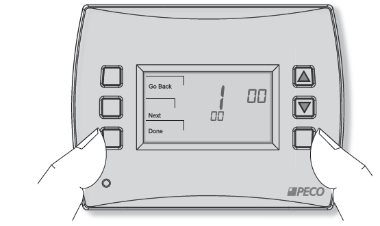
- Hold the lower right and lower left keys for five seconds.
- Press the Next or the Go Back button to select a Service Menu.
- Press ▲/ ▼ to select the Menu option.
- Press Done when complete.
The following Service Menus (SM) commonly require configuration. Please verify that these are set for your specific application. Additional configuration may be required. Refer to Table 2 for all available Service Menus.
- SM 100 = Programmable or Nonprogrammable
SM 110 = System Type - SM 120 = Fan Control
- SM 130 = Reversing Valve
- SM 240 = Number of Program Periods
- SM 260 = Temperature Format (°F or °C)
- SM 340 = Keypad Lockout
WIRING: TERMINAL DESIGNATIONS
- Connect wires for the appropriate system type (Table 1).
WARNING: DISCONNECT POWER BEFORE BEGINNING INSTALLATION.
- CAUTION: Use copper wire only. Insulate or wire-nut all unused leads.
- Use care to avoid electrostatic discharge to the thermostat
- CAUTION: Do not connect unused wires together
- ALL ELECTRICAL LOADS MUST BE CONNECTED TO TERMINAL C (24 VAC).
TABLE 1. TERMINAL BLOCK DESIGNATIONS
| C | 24 VAC, Unswitched side | C | 24 VAC, Unswitched side |
| W1 | Stage 1 Heat | B/O | Reversing Valve |
| W2 | Stage 2 Heat | AUX | Auxiliary Heat |
| G | FAN | G | FAN |
| A | A | ||
| E | E | ||
| Y1 | Stage 1 Cool | Y1 | Compressor Stage 1, Heat/Cool 1 |
| Y2 | Stage 2 Cool (or Dehumidify) | Y2 | Compressor Stage 2 Heat/Cool 2
(or Dehumidify) |
| RH | 24 VAC Power for heating, switched side | RH | 24 VAC Power for heating, switched side |
| RC | 24 VAC Power for cooling, switched side | RC | 24 VAC Power for cooling, switched side |
| SC | Sensor Common | SC | Sensor Common |
| S1 | Indoor Remote Sensor | S1 | Indoor Remote Sensor |
| S2 | Occupancy Sensor | S2 | Occupancy Sensor |
TABLE 2. ADVANCED CONFIGURATION: SERVICE MENUS
Some Service Menus may not be available, depending on the system type (SM 110).
| MENU | FEATURE | OPTIONS | STD. DEFAULT | DESCRIPTION / COMMENTS |
| 100 | Schedule Format | 0-3 | 1 | Select the schedule format on the T4000 Series. (Menu not available on non-programmable thermostats.)
0 = nonprogrammable 1 = programmable 2 = 5-1-1 schedule 3 = 5-2 schedule |
| 101 | Daylight-Saving Time | 0,1 | 0 | Select daylight-saving time as it follows the standard format in the U.S.: It begins on the second Sunday of
March at 2:00 AM and ends on the first Sunday of November at 2:00 AM. 0 = Disabled 1 = Enabled (2007 U.S. Format) |
| 110 | System Type | 1-13 | 1 | Select the appropriate system configuration (determines available Service Menus).
1 = 1 Heat/1 Cool conventional 2 = 1 Heat/1 Cool heat pump 3 = Heat only without a fan (2-wire systems) 4 = Heat only with fan 5 = Cool only 6 = 2 Heat/1 Cool heat pump (with auxiliary heat) 7 = 2 Heat/2 Cool multistage conventional 8 = 2 Heat/ 1 Cool multistage conventional 9 = 1 Heat/ 2 Cool multistage conventional 10 = 2 Heat/ 2 Cool heat pump (no auxiliary heat) |
| 120 | Fan Control (heating) | 0,1 | 0 | 0 = Fossil Fuel: Gas/Oil/Propane heat (equipment controls heating fan) 1 = Electric Furnace (thermostat controls heating fan) |
| 130 | O/B Reversing valve | 0,1 | 0 | When 0, output is active for cooling. When 1, output is active for heating. 0 = (O) Active with cooling
1 = (B) Active with heating |
| 140 | Auxiliary Heat | 0,1 | 0 | 0 = Electric backup heat
1 = Fossil fuel backup heat |
| 150 | Backlight | 0,1 | 0 | 0 = Backlight temporarily on
1 = Backlight always on (low intensity, 24V only) |
| 170 | Remote Sensor | 0-1 | 0 | Select sensor if used. Contact PECO for information on the T4000 Series Indoor Remote Zone Sensor.
0 = No Remote Sensors 1 = Indoor Sensor Only |
| 240 | Number of Program Periods | 2; 4 events | 4 | 2 = 2 events per day (Selections OCC1 and UnOcc1)
4 = 4 events per day (Selections Occ1-UnOcc1-Occ2- UnOcc2) |
| 250 | Clock format | 12 or 24 Hours | 12 | 12 = 12-hour clock mode 24 = 24-hour clock mode |
| 260 | Temperature Format (°F or °C) | 0,1 | 1 | 0 = Celsius
1 = Fahrenheit |
| 270 | Fan Off Delay Heat | 0-99 Seconds | 0 | Select the amount of time (in seconds) that the fan will run after the thermostat heat outputs are turned off. |
| 280 | Fan Off Delay Cool | 0-99 Seconds | 0 | Select the amount of time (in seconds) that the fan will run after the thermostat cool outputs are turned off. |
| 290 | Range Low | 50-90 °F or
10-32°C |
50°F (10°C) | Choose the lowest selectable temperature setpoint value. |
| 300 | Range High | 50-90 °F or
10-32°C |
90°F (32°C) | Choose the highest selectable temperature setpoint value. |
| 310 | Setback Low | Off; 50-82°F or 11-27°C | 55°F (13°C) | Select the heat setpoint for setback mode. 0 = Off
50-82°F (11-27°C) |
| 320 | Setback High | Off; 58-90°F or 11-32°C | 90°F (32°C) | Select the cool setpoint for setback mode. 0 = Off
58-90°F (11-32°C) |
| 330 | Zone Temp Offset | +/-9°F or +/- 4.5°C | 0°F (18 °C) | Adjusts the displayed value; may differ from actual zone temperature. |
| 340 | Keypad Lockout | 0-3 | 0 | Restricts access to certain features of device; Service Menu still available if enabled. 0 = No key pad lockout (Default)
1 = Disables Schedule and System keys 2 = Disables Schedule, System, and Fan keys 3 = Disables all keys |
| MENU | FEATURE | OPTIONS | STD. DEFAULT | DESCRIPTION / COMMENTS |
| 341 | Enable Pin Access | 0,1 | 0 | Applies a 3 digit access code to enter Service Menu 342 0 = Disable,
1 = Enable |
| 342 | Set PIN Access Code | 000-999 | 000 | Choose a 3-digit code. |
| 350 | Fan Mode Enable | 1-3 | 3 | 1 = ON: Fan is turned on regardless of demand.
2 = Auto: Fan is turned on according to heating or cooling demand. 3 = ON or Auto: Allows occupant to select either 1 or 2 above. |
| 360 | System Mode Enable | 0-3 | 1 | Allows ability to determine which system modes the occupant can select.
0 = OFF, Auto (0 is NOT valid for following configurations: Heat Only; Cool Only.) 1 = OFF, Heat, Cool, Auto 2 = OFF, Heat, Cool 3 = Heat, Cool, Auto |
| 380 | Minimum Deadband Adjustment | 3-10°F, 1.5-5°C | 3°F | Select a changeover deadband value to prevent short cycling between heating and cooling modes.
The value is adjustable to meet various HVAC system requirements. |
| 390 | Pre-Occupancy Purge | 0-3 hours | 0 hours | Select to energize fan for selected number of hours (0-3) prior to all occupied events. |
| 395 | Maximum Override Time Limit | 0=Time until next event; or
1-4 hours |
3 | Restricts the duration that a temporary hold can be set. The temporary hold is limited by the
maximum amount of time as defined in this Service Menu. 0 = Remainder of time until the next scheduled event. 1 = 1 Hour 2 = 2 Hours 3 = 3 Hours 4 = 4 Hours |
| 400 | Cycles Per Hour (CPH)
Cooling Stage 1 |
0-6 CPH | 0 CPH | Defines the number of cycles per hour for cooling (Stage 1). Select 0 to enable ON-OFF
control for Stage 1 cooling. |
| 410 | Cycles Per Hour (CPH)
Cooling Stage 2 |
0-6 CPH | 0 CPH | Defines the number of cycles per hour for cooling (Stage 2). Select 0 to enable ON-OFF
control for Stage 2 cooling. |
| 420 | Cycles Per Hour (CPH)
Heating Stage 1 |
0-12 CPH | 0 CPH | Defines the number of cycles per hour for heating (Stage 1). Select 0 to enable ON-OFF
control for Stage 1 heating. |
| 430 | Cycles Per Hour (CPH)
Heating Stage 2 |
0-12 CPH | 0 CPH | Defines the number of cycles per hour for heating (Stage 2). Select 0 to enable ON-OFF
control for Stage 2 heating. |
| 450 | Cycles Per Hour Heating Stage 3 | 0-12 CPH | 0 CPH | Defines the number of cycles per hour for heating. Select 0 to enable ON-OFF control for
Heating Stage 3. |
| 460 | Heat Recovery Rate | 0-18°F/Hr
0-10°C/Hr |
0°F/Hr | Defines the rate at which the device achieves the heat comfort setpoint. Select 0 to disable ramp recovery. |
| 470 | Cool Recovery Rate | 0-18°F/Hr
0-10°C/Hr |
0°F/Hr | Defines the rate at which the device achieves the cool comfort setpoint. Select 0 to disable ramp recovery. |
| 480 | Minimum Off Time | 1-10 minutes | 4 minutes | Sets the minimum off time for both the heat and cool output. |
| 490 | Humidity Control Enable
(Select models only) |
Selects how humidity will be controlled. When dehumidify control is enabled, the Y2 terminal becomes dehumidify.
0 = Disabled 1 = Dehumidify Control |
||
| 500 | Programmable/ Intermittent Fan | 0-2 | 0 | 0 = Disable
1 = Programmable Fan: Fan operates continuously in occupied periods or with demand in unoccupied periods. 2 = Intermittent Fan: Fan operates based on the on and off times set in menus 501 and 502. |
| 501 | Intermittent Fan On Time | 1-60 minutes | 5 minutes | Defines the on time for the Intermittent Fan. |
| 502 | Intermittent Fan Off Time | 0-60 minutes | 25 minutes | Defines the off time for the Intermittent Fan. Select 0 for continuous fan. |
| MENU | FEATURE | OPTIONS | STD. DEFAULT | DESCRIPTION / COMMENTS |
| 520 | Default Display Icons | 0-4 | 0 | Select icons that will be displayed in the Default Display screen. 0 = Time, Temp, Setpoint (SP)
1 = Time, Temp 2 = Time 3 = Temp 4 = None |
| 530 | Revision | — | — | Displays firmware revision information (for technician); not adjustable. |
| 540 | Factory Default Reset | 0,1 | 0 | Select 1 (enable) to restore the factory default settings for the thermostat. Select 0 to disable. 0 = Disable
1 = Enable Note: Press the “Done” key to complete the process. |
| 600 | System Test Main Output (Cool) | 0-2 | 0 | Select the option to activate fan output for 10 minutes; select 0, Done, or a different Service Menu to disable. 0 = Disable (Default)
1= Cool Stage 1 2 = Cool Stage 2 |
| 610 | System Test Main Output (Heat) | 0-3 | 0 | Select an option to activate the fan output for 10 minutes; select 0, Done or a different Service Menu to
disable. Note: Outputs will be activated based upon the system configuration. 0 = Disable (Default) 1 = Heat Stage 1 2 = Heat Stage 2 3 = Heat Stage 3 |
| 620 | System Test Fan Output | 0,1 | 0 | Select 0 or 1 to activate the fan output for 10 minutes; select 0, Done, or a different Service Menu to disable. Note: For Service Menus 610 and 620, outputs activated based upon the system configuration 0 = Disable Fan Output
1 = Enable Fan Output Note: Outputs will be activated based on the system configuration. |
COPYRIGHT 2015 PECO ASTRONICS. ALL RIGHTS RESERVED P/N 70930 3220-2322 REV 01
REFERENCE:
DOWNLOAD MANUALS:
Peco T4522-001 Programmable Thermostat User Guide
OTHER MANUALS:
Peco T4000 Programmable Thermostat Installation Guide
Peco T4000 Programmable Thermostat Operating Manual
![]()
Leave a Reply