
Prostat PSP4272 Residential Smart Wi-Fi Thermostat
CAUTION Follow the Installation Instructions before proceeding. Set the thermostat mode to “OFF” prior to changing settings in setup or restoring Factory
FCC Compliance Statement
This equipment has been tested and found to comply with the limits for an intentional radiator, pursuant to Part 15, subpart C of the FCC rules. These limits are designed to provide reasonable protection against harmful interference in a residential installation. This equipment generates, uses, and can radiate radio frequency energy and, if not installed and used in accordance with the instructions, may cause harmful interference in radio communications. However, there is no guarantee that interference will not occur in a particular installation. If this equipment does cause harmful interference to radio or television reception, which can be determined by turning the equipment off and on, the user is encouraged to try to correct the interference by one or more of the following measures:
- Reorient or relocate the receiving antenna.
- Increase the separation between the equipment and the receiver.
- Connect the equipment to an outlet on a circuit different from that of the receiver.
- Consult the dealer or an experienced radio or TV technician for help.
Notice: Only peripherals complying with FCC limits may be attached to this equipment. Operation with noncompliant peripherals or peripherals not recommended by ProStat+™ is likely to result in interference to radio and TV reception. Changes or modifications to the product, not expressly approved by ProStat+ could void the user’s authority to operate the equipment.
FCC – INDOOR Mobile Radio Information
To comply with FCC/IC RF exposure limits for general population / uncontrolled exposure, the antenna(s) used for this transmitter must be installed to provide a separation distance of at least 20 cm from all persons and must not be co-located or operating in conjunction with any other antenna or transmitter. This Device complies with Industry Canada License-exempt RSS standard(s). Operation is subject to the following two conditions: 1) this device may not cause interference, and 2) this device must accept any interference, including interference that may cause undesired operation of the device.
Under Industry Canada regulations, this radio transmitter may only operate using an antenna of a type and maximum (or lesser) gain approved for the transmitter by Industry Canada. To reduce potential radio interference to other users, the antenna type and its gain should be so chosen that the equivalent isotropically radiated power (e.i.r.p.) is not more than that necessary for successful communication. We, ProStat+, declare under our sole responsibility that the device to which this declaration relates: Complies with Part 15 of the FCC Rules. Operation is subject to the following two conditions: (1) this device may not cause harmful interference, and (2) this device must accept any interference received, including interference that may cause undesired operation.
This thermostat has the ability to receive updates to its firmware. Periodically firmware updates are released by the manufacturer to add features and/or performance enhancements. This manual was produced reflecting the most current firmware/feature set at the time of publication, firmware rev. 1.0. Firmware releases after rev. 1.0 may not be adequately depicted in this manual. Please refer to the appropriate website or contact your place of purchase to learn about changes to the thermostat after firmware release 1.0.
IMPORTANT:
Follow Installation Instructions carefully. Disconnect Power to the Heater/Air Conditioner before removing the old thermostat and installing the new thermostatCongratulations and thank you for purchasing your new ProStat+ Smart Wi-Fi thermostat. This guide is intended to help you install and setup the basic features of your thermostat.
Features
- Geofencing for automatic Home and Away settings using the ProStat+ app location services on your mobile device
- Choose 7-Day, 5/1/1 Day or 1-Day Programming
- 365-Day Vacation Programming (When Connected to ProStat+ Web Portal)
- Setpoint Limiting
- Adjustable Timers & Deadbands Between Stages
- Adjustable Staging Turnoffs, Deenergize At Deadband or Keep Active Until Setpoint
- Can Be Used to Comply with 2016 Title 24, Part 6 Thermostat Requirements
- Programmable Fan Runs 5 – 60mins Per Hour with Adjustable Start/Stop Times
- Outdoor Sensor Ready With Hi/low Readouts for the Day
- Condensate Overflow Warning System
- Control To, or Monitor a 2nd Remote Sensor, Baby’s Room or Game Room, etc.
- Choice of English, Spanish or French for Scrolling Display
- OEM-branded Equipment Badges Included
Terms
- Auto-Changeover: A mode in which the thermostat will turn on the heating or cooling based on the room temperature demand.
Cool Setpoint: The warmest temperature that the space should rise to before cooling is turned on (without regard to the dead band). - Deadband: The number of degrees the thermostat will wait, once a setpoint has been reached, before energizing heating or cooling.
- Differential: The forced temperature difference between the heat setpoint and the cool setpoint.
- Heat Setpoint: The coolest temperature that the space should drop to before heating is turned on (without regard to the dead band).
- Icon: The word or symbol that appears on the thermostat display.
- Mode: The current operating condition of the thermostat (i.e. Off, Heat, Cool, Auto, Program On). Programmable Thermostat: A thermostat that has the capability of running Time
- Period Programming. Reheat: Running the cooling and 2nd stage strip heaters at the same time in order to dehumidify the air without
significantly cooling down the room temperature. - Temperature Swing: Same as Deadband.
- Time Period Programming: A program that allows the thermostat to automatically adjust the heat setpoint
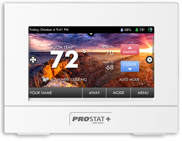
About Your Thermostat
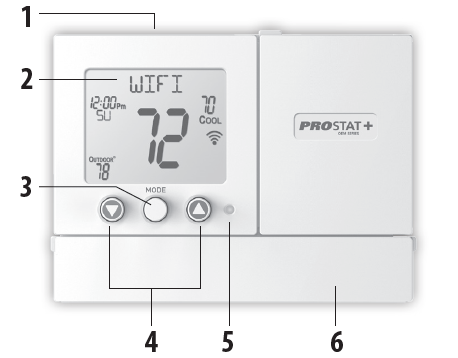
Front Display
- AmbientLight Sensor
- Backlit, Scrolling LCD Display
- MODE Button
- Warmer & Cooler Buttons
- Heat or Cool Indicator Heat = Red, Cool = Green
- Setup Buttons behind door
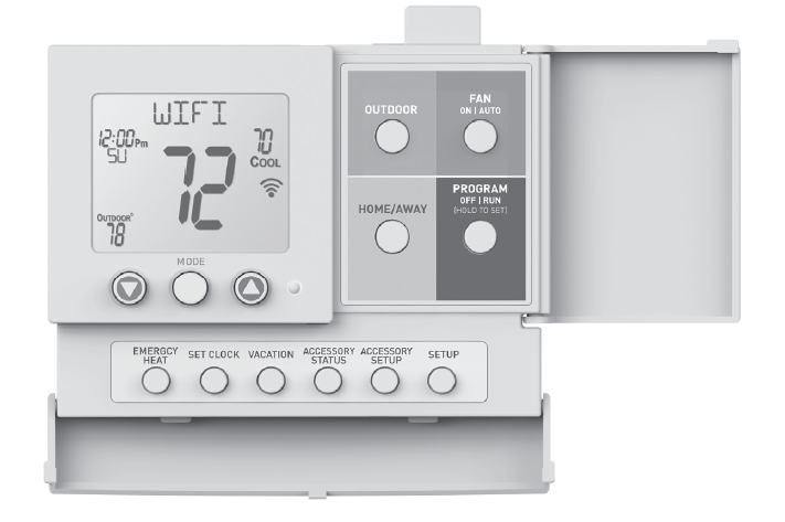
Table for button presses that are required for entering various menus
TO ENTER THE MENUS BUTTON PRESS
- Setup Steps Press the SETUP button
- Time Schedule Press the SET CLOCK button
- Emergency Heat Press the EMERGENCY HEAT button
- Lockout Buttons MODE, Up & Down for 2 seconds
- Calibration Press SETUP for 10 seconds
- Wireless Setup Press the ACCESSORY SETUP button
Button Callouts Inside Doors
Display Features
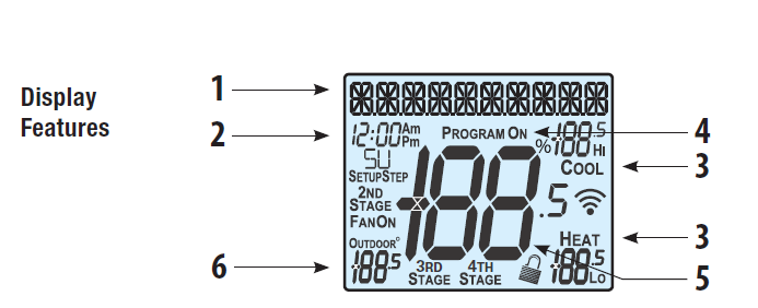
- The scrolling display will be used to help you easily navigate the setup screens in the thermostat.
- Clock with Day of the Week
Indicates the current time and day. This clock is also used to program the time period schedules. - Mode Indicators Select the operational mode of the equipment.
HEAT – Indicates the heating mode.
COOL – Indicates the air conditioning mode.
HEAT & COOL – Indicates the system will automatically change over between heat and cool modes as the temperature varies. Neither Heat nor Cool – Indicates heating and cooling is turned off. - Program ON icon
Indicates that Time Period Programming is running or is enabled to be set. - Room Temperature Display
Indicates the current room temperature and displays the outdoor temperature when selected. - Outdoor icon
Indicates the temperature displayed is from the optional outdoor sensor or the ProStat+ Web Portal.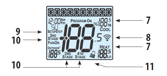
- Desired Set Temperature
Indicates desired room temperature(s). Also displays the highest and lowest temperatures for the day. - Wi-Fi icons
One dot indicates the thermostat recognizes the wireless module. The “full” icon indicates the thermostat is currently connected to the Local access point, via the optional Wi-Fi Module. - Setup Step icon
Indicates the step number when the thermostat is in setup mode. - 2nd, 3rd and 4th Stage icons
Indicates what stage of cooling or heating is currently energized.  icon
icon
This indicates the keypad has been locked.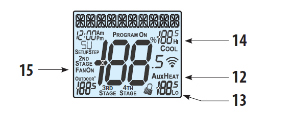
- AuxHeat icon
Indicates 2nd stage electric strip heat is being used when the thermostat is programmed for Heat Pump operation. Only the Aux icon will appear during Cool to Dehumidify to indicate Reheat operation. - 13 Lo icon
Indicates the lowest recorded outdoor temperature for the day.* - Hi
iconIndicates the highest recorded outdoor temperature for the day.* - Fan On icon
Indicates constant, continuous fan operation. When Fan On is not lit – indicates the fan will only operate when necessary to heat or to cool.
Hi and Lo Temperatures for the day reset at midnight and require an outdoor sensor or ProStat+ Skyport connectivity.
Basic Operation
During Setup and Programming
Press the WARMER or COOLER buttons to modify the selection. Press the MODE button to advance and confirm through the setup steps.
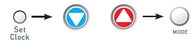
Setting the Clock and Day*
Not available when connected to a ProStat+ Account Press the SET CLOCK button. Adjust the clock using the WARMER or COOLER buttons. Press MODE to advance to the day
setting. Adjust the day using the WARMER or COOLER buttons. Press the SET CLOCK button to confirm settings.
TIP: To adjust the time by hours press and hold the FAN button while pressing the WARMER or COOLER buttons
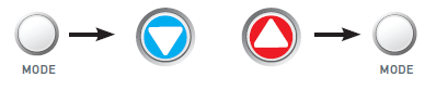
Selecting the Heat or Cool Mode
The select mode by pressing the MODE button.
Heating Only – Only the heating operation will be controlled by the thermostat in this mode.
Cooling Only – Only the cooling operation will be controlled by the thermostat in this mode.
Heating or Cooling (Auto-Changeover) – AUTO will automatically select heat or cool based on room temperature demand.
Neither Heat nor Cool (OFF) – OFF indicates heating and cooling is turned off.
Tip: When changing MODE, the new mode will temporarily be shown on the scrolling display
Selecting Your Desired Temperature (adjusting the setpoints)
Auto-Changeover Mode
Pressing the WARMER or COOLER buttons in Auto mode will adjust both the heat and cool setpoints simultaneously. To adjust the heat and cool setpoints individually, choose HEAT mode to adjust the heat setpoint, and COOL mode to adjust the cool setpoint, then return to AUTO mode.

Heat or Cool Mode
Pressing the WARMER or COOLER buttons in Heat or Cool mode will adjust only the heat or cool set temperature.
Using the Fan Button
Fan On indicates constant fan operation. Fan On is not allowed when the thermostat is in the OFF mode. Pressing the FAN button toggles this feature on or off. Fan auto will allow the fan to run only when there is a heat or cool demand.

Viewing the Temperature Sensors
OUTDOOR TEMP – Press the OUTDOOR button to view the current outdoor temperature. The high and low temperatures for the day will also be displayed. The high and low temperatures reset at 12:00 am. Press the OUTDOOR button again to return to normal operation. If the thermostat is connected to Skyport; upon pressing the OUTDOOR button the scrolling display will read “Forecast”. The forecasted high and low temperatures for the day will be displayed. Press the OUTDOOR button again to view any connected wired sensor (REMOTE or SUPPLY).

Note: If no outdoor sensor is connected, and there isn’t outdoor temperature via Wi-Fi, then 2 dashes [- -] will
appear with the first button press.
REMOTE/SUPPLY TEMP – Press the Accessory Status button to view linked wireless wired sensors and other accessories. Press the Accessory Status button to return to the main screen. Setup step #42 selects the use of the wired temperature sensor

Setup Step Table
| Step# Description | Pg# | Range | FD | |
| 1 | Prog Mode | Non, 1 Day, 5/2 Day, 7 Day | 7 | |
| 2 | Available Modes | Heat/Cool/Auto/Off, Heat/Cool
/Off, Heat/Off, Cool/Off |
Heat/Cool
/Auto/Off |
|
| 3 | Backlight | On, Off | Off | |
| 4 | Backlight Level | Off thru 7 levels of brightness | Level 5 | |
| 5 | Night Dimmer | On/Off | Off | |
| 6 | Night Dimmer Brightness | Off thru 7 levels of brightness | 2 (20%) | |
| 7 | Night Dimmer Start Time | 12A-12A | 8:00P | |
| 8 | Night Dimmer Stop Time | 12A-12A | 6:00A | |
| 9 | Current Service Filter Runtime Hours | 0-1999 Hours | 0 | |
| 10 | Current Service Filter Calendar Days | 0-720 Days | 0 | |
| 11 | Current UV Lamp Calendar Days | 0-720 Days | 0 | |
| 12 | Set Service Filter Runtime Hours | 0-1950 hours | 0 | |
| 13 | Set Service Filter Calendar Days | 0-720 Days | 0 | |
| 14 | Set UV Lamp Calendar Days | 0-720 Days | 0 | |
| 15 | Language | English, Espanol, Francais | English | |
| 16 | Scrolling Method | “L-R Slow, L-R Fast, Word L-R Slow, Word L-R Fast, Whole Word L Slow, Whole Word
R Slow, Whole Word Ctr. Fast, Whole Word Ctr. Slow” |
“Whole Words Center Fast” | |
| 17 | Setpoint Limits | No, Use | No | |
| 18 | Max Heat Setpoint | 35 – 99 Degrees | 74 | |
| 19 | Min Cool Setpoint | 35 – 99 Degrees | 70 | |
| 20 | Cycles Per Hour | No Limit, 2, 3, 4, 5, 6 | 6 | |
| 21 | Compressor Minimum Off Minutes | 0, 3, 5 Minutes | 5 | |
| 22 | Min. Heat/Cool Setpoint Difference | 0 – 6 Degrees | 2 | |
| 23 | Number of Heat Stages | 0 – 3 | 2 | |
| 24 | Number of Cool Stages | 0 – 2 | 1 | |
FD = Factory Default Setting Installer Setup Steps (see Installer Manual for more details)
| Step# Description | Pg# | Range | FD | |
| 25 | Number Of Compressor Stages | 1, 2 | 1 | |
| 26 | Number of Aux Stages | 0, 1, 2 | 0 | |
| 27 | 1st Stage Deadband | 1 – 6 Degrees | 2 | |
| 28 | 2nd Stage Deadband | 0 – 10 Degrees | 2 | |
| 29 | 3rd Stage Deadband | 0 – 10 Degrees | 2 | |
| 30 | 4th Stage Deadband | 0 – 10 Degrees | 2 | |
| 31 | Minutes Between 1st and 2nd Stage | 0 – 60 Minutes | 2 | |
| 32 | Minutes Between 2nd and 3rd Stage | 0 – 60 Minutes | 2 | |
| 33 | Minutes Between 3rd and 4th Stage | 0 – 60 Minutes | 2 | |
| 34 | 2nd StageTurnoff Point | Deadband, Setpoint | Deadband | |
| 35 | 3rd StageTurnoff Point | Deadband, Setpoint | Deadband | |
| 36 | 4th Stage Turnoff Point | Deadband, Setpoint | Deadband | |
| 37 | Fan Program | On, Off | Off | |
| 38 | Minutes of Fan Runtime | 0-60 | 0 | |
| 39 | Fan Program Start Time | 12:00A – 12:00A | 7:00A | |
| 40 | Fan Program Stop Time | 12:00A – 12:00A | 9:00A | |
| 41 | Wired Sensor Type | Remote, Supply | Remote | |
| 42 | Control to Temp Source | Thermostat, Wired Remote*, Wireless Remote, Average of Wireless Remotes, Average Thermostat and Wired Remote*, Average All Sensors.
*Option only if prior step = “Remote” |
Thermostat | |
| 43 | Wireless Remote to Use | list of wifi sensors currently linked to thermostat.
* This step only appears if prior step = “Wireless Remote” |
first linked sensor in list | |
| 44 | Fan Off Delay | 0 – 120 Seconds | 0 | |
| 45 | F/C | Fahrenheit (F), Celsius (C) | F | |
| 46 | Comfort Recovery | On, Off | Off | |
| 47 | Dry Contact Polarity | Open, Closed | Open | |
| Step# Description | Pg# | Range | FD | |
| 48 | Dry Contact Use | Condensate, Vacation, FDD | Vacation | |
| 49 | Skyport | On, Off | On | |
| 50 | Local API | On, Off | Off | |
| 51 | ADR | On, Off | On | |
| 52 | Price Dependant Action | Observe Setpoint Offset,
Observe Static Setpoints |
Observe set-
point offsets |
|
| 53 | Event Max Cool Setpoint | 65 – 90 | 90 | |
| 54 | Event Min Heat Setpoint | 50 – 85 | 50 | |
| 55 | Static Cool Setpoint | 65 – 85 | 82 | |
| 56 | Static Heat Setpoint | 65 – 85 | 60 | |
| 57 | Cool Setpoint Offset | 1 to 10 | 4 | |
| 58 | Heat Setpoint Offset | -1 to -10 | -4 | |
| 59 | Press Fan To Clear All Messages | |||
Programming a Daily Schedule
To enter the Setup screens, press the SETUP button, then press MODE. Use the WARMER or COOLER buttons to adjust the value of your selection. Press MODE to advance to the next setup step. Press SETUP again to leave the setup screens.
Selecting Your Time Period Schedule (setup step 1) : Press the Setup button
- This thermostat may be configured to be programmable or nonprogrammable.
- 7-Day Program – Allows all seven days to be programmed independently.
- Non-Program – No advanced time period programming available.
- 1-Day Program – Allows one 24-hour day to be programmed. This same schedule will be repeated every day the program is set to run.
- 5/1/1 Day Program – Allows weekdays, Saturdays, and Sundays to be programmed independently.
Selecting Your Available Modes (setup step 2)
- Auto-Changeover – Allows the thermostat to turn on heating or cooling based on room temperature demand.
- Also allows the manual selection of HEAT only or COOL only and OFF.
- Heat and Cool – Allows the thermostat to turn on heating or cooling depending on which one has been manually selected. Auto-Changeover is not available when this is selected.
- Heat Only – Allows the thermostat to only turn on the HEAT or OFF modes.
- Cool Only – Allows the thermostat to only turn on COOL or OFF modes.
Time Period Programming
- To enable (RUN) or turn ON the Time Period Schedule press the Program button momentarily.
- To turn Off the Time Period Schedule press this button again.
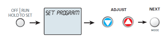
- To alter the Time Period Schedule settings; press & hold this button for 5 seconds until the SET PROGRAM prompt appears.
- Modify the settings with the Warmer and Cooler buttons. Use the MODE button to advance through the steps. Press the
- Program button again to leave the setup screens
Once the Set Program prompt appears the Mode button will step you through the settings as follows: This thermostat features four programmable time periods per 24-hour day: Morning, Day, Evening, and Night. The start time for each time period is adjustable. The stop time for each time period is the start time for the next period. Each time period or day part may be individually disabled. Select the Day to Program – Press the WARMER or COOLER to select the desired Day or Week Part in the case of 5-2 (weekday – weekend) programming.
Enable/Disable Morning Period – Press the WARMER or COOLER to select ON or OFF. If the default ON is selected, then the Morning period will run complete with the Mode and Set Points selected. If OFF is selected then the Morning day part will be skipped and the thermostat will use the next day part that is enabled.
Select Morning Mode – Press the WARMER or COOLER to select the desired mode, which includes OFF. You may be limited by the available modes in advanced Installer setup step#2. Press MODE to advance to the next step.
Select Morning Start Time – Press the WARMER or COOLER buttons to adjust the time of day desired. Press MODE to advance to the next step.
Select Morning Cool Setpoint – Press the WARMER or COOLER buttons to adjust the cool setpoint desired. This step will
appear if Cool or Auto Mode was selected in the step where the Morning mode is specified. Press MODE to advance to the next step.
Select Morning Heat Setpoint – Press the WARMER or COOLER buttons to adjust the heat setpoint desired. This step will appear if Heat or Auto Mode was selected in the step where the Morning mode is specified. Press MODE to advance to the next step. Repeat Enable, Mode, Start Time, and Setpoint programming for Day, Evening, and Night. “Copy Current Day to Next Day” is available – Press the UP button to Copy the current day’s program to the next day. Press MODE again to continue copying the following day. Press the PROGRAM Button to exit Time Period Programming at any time
Advanced Features & Operation
Backlight (Setup Steps 3-8): Press Setup and then Mode over and over to advance to step #3
Backlight (Setup Step 3)
- Off – Backlight turns on only with a button press and turns off after 8 seconds.
- On – Backlight is on continuously.
Backlight Intensity Level (Setup Step 4) – The backlight can be adjusted between Off and seven levels of brightness
- Night Dimmer (setup step 5) – Selecting On allows for automatic dimming of the display at night.
- Night Dimmer Brightness (setup step 6) – Off through seven levels of brightness
- Night Dimmer Start Time (setup step 7)
- Night Dimmer Stop Time (setup step 8)
Emergency Heat
Only available if you have a Heat Pump installed. To initiate the Emergency Heat feature, press the EMERGCY HEAT button. During Emergency Heat operation the thermostat will turn on the fan and auxiliary stages of heat when there is a demand for heat. The 1st stage of heating and all stages of cooling will be unavailable. To exit Emergency Heat, press the EMERGCY HEAT button. Please follow the instructions included with the PSPAC-PWF Wi-Fi module to connect to an Access Point or view status. The general instructions are below.
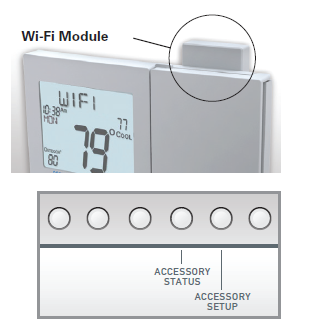
Wi-Fi Module
If the is present on the display then the thermostat is connected to the Wi-Fi Access Point. If just of this icon appears, then just the Wi-Fi module is recognized. Press the Accessory Status button, then press either the Cooler button to view connected Wi-Fi sensors, OR press the Warmer button to view the Wi-Fi status and settings. Press the MODE button to step through the connected sensors or the Wi-Fi status screens listed below.
- Wi-Fi status (connecting, connected with duration of the connection, etc.)
- Signal strength
- Access point name
- IP address h. Module version MAC address
- ProStat+ Skyport status (connecting, connected with duration of the connection, etc.)
- Local API status (Enabled, Disabled)
- Module version
At any time press the Accessory Status button to leave the status screens. Press the Accessory Setup button to enter Wi-Fi or ProStat+ Skyport setup: Press the Cooler button to configure Wi-Fi settings. Press the Warmer button to join this thermostat to a ProStat+ account. If the thermostat is connected to Wi-Fi and the Internet, a Device ID will appear on the scrolling display of the thermostat. You will enter this code to add this thermostat to your ProStat+ account via a browser or the ProStat+ mobile app. Note: To connect to ProStat+ Skyport, Setup Step #73 must be set to on
Resetting the thermostat to Factory Defaults (for default values see Advanced Setup Table)
If, for any reason, you desire to return all the stored settings back to the factory default settings, follow the instructions below.
WARNING: This will reset all Time periods and Advanced Programming to the default settings. Any information entered prior to this reset will be permanently lost.
- Press and hold SETUP for 10 seconds. All icons will appear on the display. Keep pressing the SETUP button until you see this screen.
- After all the icons appear, release SETUP. Press and hold FAN for 5 seconds. DEFAULTS will appear on the display. Keep Pressing the FAN button until you see this screen.
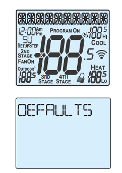
- After DEFAULTS appears, release FAN. Press SETUP to return to normal operation
Innovation, Science, and Economic Development Canada ICES-003 Compliance Label: CAN ICES-3 (B)/NM8-3(B)
Reference:
Download Manual:
Prostat PSP4272 Residential Smart Wi-Fi Thermostat User Manual
![]()
Prostat PSP4272 Residential Smart Wi-Fi Thermostat User Manual
Leave a Reply