
HITACHI PC-2H2 REMOTE CONTROLLER Thermostat
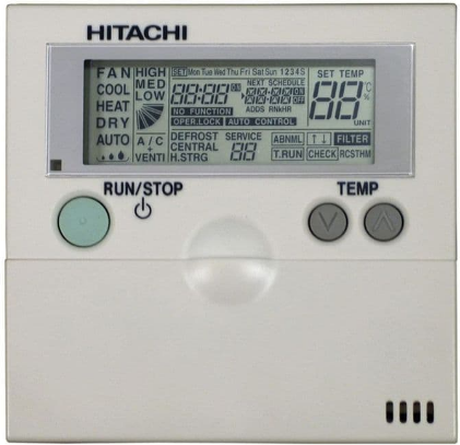
INSTALLATION OF REMOTE CONTROL
- DO NOT pour water into the remote controller (hereafter called “controller”). These products are equipped with electrical parts. If poured, it will cause a serious electrical shock.
- DO NOT operate switches by wet hand. It may cause an electrical shock.
- In case that the protective devices often function or the operation switches do not function well, turn OFF the main\ power supply and contact your distributor or dealer of HITACHI.
- In case that other abnormalities are found, stop the system, turn OFF the main power supply and contact your distributor or dealer of HITACHI.
- DO NOT perform installation work and electrical wiring connection by yourself.
- In case that a service work such as repair, maintenance, etc. is required, contact your distributor or dealer of HITACHI.
- DO NOT modify the electrical wiring. It may cause serious accidents.
- DO NOT install the indoor unit, outdoor unit, controller and cable within approximately 3 meters from strong electromagnetic wave radiators such as medical equipment.
- DO NOT use the multi-core wire for electrical wiring.
- If used, some signals of one system transfer to the other system, the signals interfere each other and it cause the malfunction.
- DO NOT use thin shield wire such as CPEVS. Such wires with big electrostatic capacity make the transmission signal dull end the transmission error may occurs in case of long distance wiring.
- DO NOT run any cable for transmission and signal along the power line (220-240V, 380-415V).
- DO NOT run any cable for transmission and signal along other cables for transmission and signal.
- If the cables are required to be run along, keep a distance more than 30 cm between each cables, or insert the cables for each transmission system into the metal conduit tube and ground one end of the conduit tube.
Location of Remote Controller
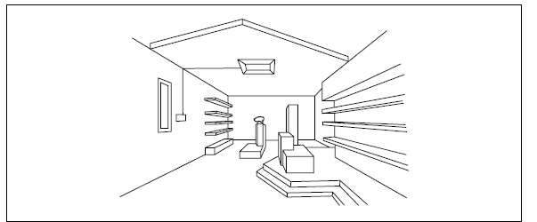
- Select a suitable place for handling and determine the installation place of the controller with the customer’s acceptance.
- Do not install the controller at such places as;
- where children can touch
- where the air from the air conditioner is directly discharged
- where there is oil vapor and the oil is dispersed
- where the humidity is high.
- Especially in case that a remote control thermostat is used, select the installation place in consideration with the following points;
- where the average room temperature can be detected
- where the thermostat is not exposed directly to the sun
- where the heat sources is not near around
- where the thermostat is not affected with the outdoor air by opening and closing doors
- where the air from the air conditioner is directly discharged
- Pay attention to the following points in case that the controller is installed in a place where there is medical equipment radiating electromagnetic waves.
- DO NOT install the controller in a place where electromagnetic waves are radiated directly toward the remote control cable and the controller.
- Keep a distance more than 3 meters away from the equipment radiating electromagnetic waves.
- Keep a distance more than 3 meters away from the receiver such as radio. It may cause noises.
- Shield the controller and cables by covering with the steel box and running the cable through the metal conduit tube.
- In case that there is electric noise at the power source for the indoor unit, provide a noise filter.
- In case of installing the wireless remote control switch onto the wall, keep a distance more than 30 cm from the power line.
BEFORE INSTALLATION
Check the contents and the number of accessories in the packing.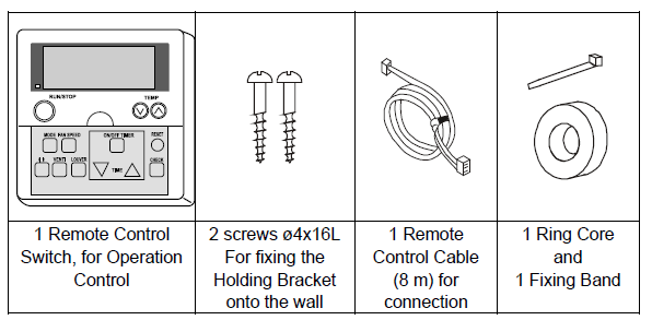
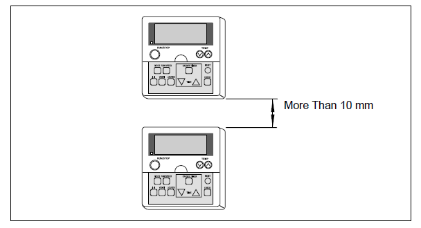
INSTALLATION SPACE
- In case of installing the controllers in vertical line, keep a distance more than 10 mm between the controllers vertically. If the distance is insufficient, the front cover of the controller can not open wide enough
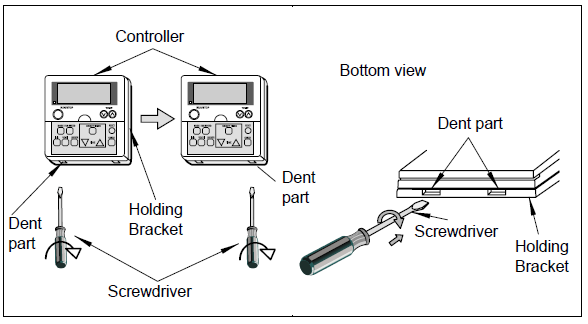
INSTALLATION PROCEDURE
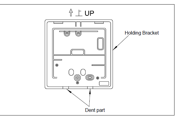
- Insert the edge of the flat head screwdriver into the dent parts at the bottom of the holding bracket, push and turn the screwdriver and remove the controller from the holding bracket as shown in the figure below
- Attach the controller to the holding bracket as follows.
- In case of exposing Remote Control Cable.

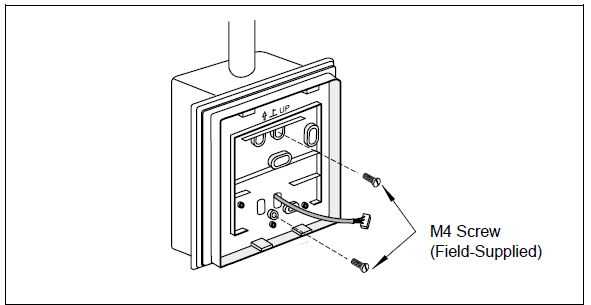
- Fix the holding bracket onto the wall as shown below
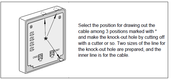
- Make the hole for drawing out the cable
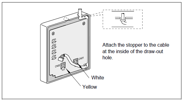
- Connect the cable to the PCB connector (yellow) of the controller, run the cable through the groove at the backside of the casing and draw out the cable from the casing.
- Fig. 6 PCB connector
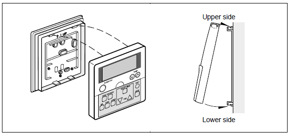
- Attaching Procedures
- Step 1: Insert the hooks of the controller to the holes on the top of the holding bracket.
- Step 2: Push the lower part toward the holding bracket.
- Step 3: When the click sound is heard, the controller is attached to the holding bracket and the mounting work is finished. Check to ensure that the 4 hooks at the position * are correctly inserted.
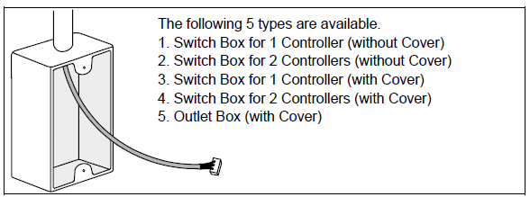
- B. When Using Switch Box.
- Field-Supplied JIS Box (JIS 8336 – 1998)
- Fix the holding bracket to the switch box
WIRING SYSTEM FOR REMOTE CONTROL SWITCH (PC-2H2)
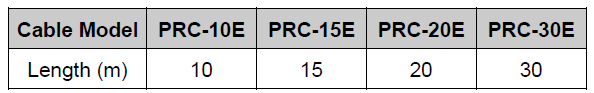
LENGTH OF WIRE CABLE FOR REMOTE CONTROL SWITCH
- Length of the standard wire cable for the optional remote control switch is 8 meters.
- Extension up to 500 meters (with 0.75mm2 CVS wire) is
- available.
- Indoor Unit: 1 set
- Remote Control Switch: 1 set
ELECTRICAL WIRING
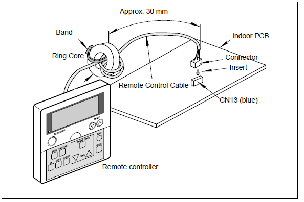
- Attach the Ring Core (black) (accessory) when installing the unit.
- Insert the remote control cable into the ring core 2 turns as shown below before connecting to the PCB. Fix the cable by using the band (accessory).
ONE REMOTE CONTROL SWITCH FOR MULTIPLE UNITS
- This remote control switch can control sixteen units, as the maximum.
- In case of this modification, wiring connection and other works shall be performed as indicated in the following procedures.
Wiring Connection for Control Circuit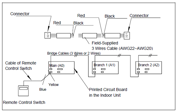
- The power source cable and the bridge cable between the indoor unit(s) and the outdoor unit(s) should be performed in accordance with the installation manual of the unit.
- The cables (0.3 mm2 wire) of different length are prepared as an option, which are fitted with connectors
- In case that a longer cable is required, the additional fieldsupplied cable shall be connected as following procedure.
- A. Prepare the cable with two wires.
- B. After checking the color of the wires, connect each wire of the same color by soldering.
- C. Insulate the soldered parts and the wires with insulation tape.
- D. The maximum total cable length of the remote control switch cable and the bridge cable(s) is 200 meters(0.3mm2 wire) or 500 meters(0.75mm2 wire).
- separate the cable more than approximately 30cm from any wires which are utilized for wires higher than 220V, or put the cable in a metal tube and earth the tube.
- Set the serial unit number by adjusting the “DSW” dip switch on the printed circuit board(s) in the indoor unit(s).
- This setting should be matched with the serial number of the bridge cable(s).
Setting of dip switch: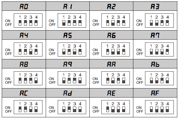
TEST RUN PROCEDURE BY REMOTE CONTROL SWITCH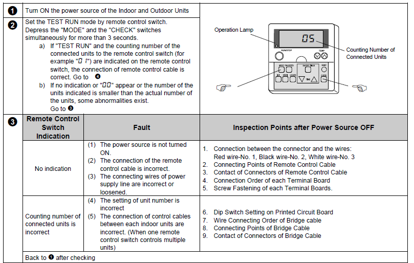
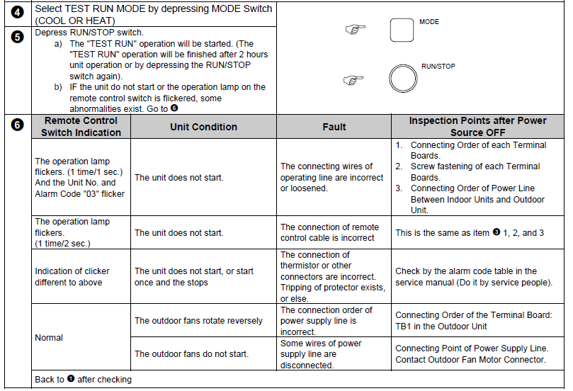
CHECK FUNCTION USING THE REMOTE CONTROL
ALARM CODES
OPTIONAL FUNCTION SETTING
Field Setting Mode
Check to ensure that the unit is stopped, press the “CHECK”switch and the “RESET” switch on the remote control switch simultaneously more than 3 seconds, and the remote control switch is changed to the field setting mode. When the remote control switch is at the field setting mode, the “SERVICE” is indicated and the “01” is flickers below the “SERVICE” indication.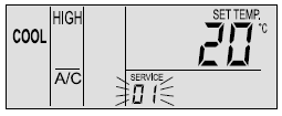
Optional Setting Mode
At the field setting mode as described in Field Setting Mode, press the “TEMP Δ” switch or the “TEMP ∇ ” switch and the number flickering below the “SERVICE” indication is changed (01 <=> 02). Set the flickering number at “01”, leave this condition for 7 seconds or press the “CHECK” switch, and the remote control switch is changed to the optional setting mode.
Selection of Indoor Unit
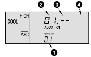
- At the optional setting mode, the indication on the remote control switch is changed as shown in the right figure.
- The indication of “01” is turned
- The address of the indoor unit which the optional function is to be set, is indicated at the segments for timer setting time indication, and the “ADDS” is indicated below.
- The refrigerant cycle number of the indoor unit for which the optional function is to be set is indicated “” and the “RN” is indicated below.
- The indication of the setting temperature is turned OFF.
- At the condition of the above item (a), press the “TEMP ∇” switch or the “TEMP Δ” switch of the remote control switch and the indoor unit for which the optional function is to be set, can be changed.
- After selecting the indoor unit, leave the condition for 7 seconds or press the “CHECK” switch, the remote control switch is changed to the optional setting mode
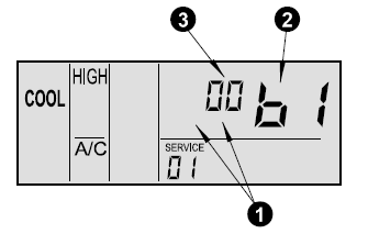
Changing of Optional Functions and Setting Conditions
- At the optional setting mode, the indication on the remote control switch is changed as shown below.
- The indications of “ADDS” and “RN” are turned OFF.
- The item number of the optional function is indicated at the segment for the setting temperature indication. Refer to the table in the next pages for the item numbers and the contents of the optional functions.
- The setting condition of the optional function item is indicated at the segments for timer setting time indication. Refer to the table in the next pages and description of each items for the indication of the setting condition and the contents of the optional function.
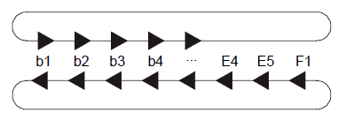
- Press the “TIME ∇” switch or the “TIME Δ” switch, the optional function item is changed as shown below.
- When pressing the “TIME Δ” switch
- When pressing the “TIME ∇” switch
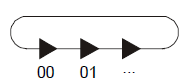
- Press the “CHECK” switch, and the setting condition of the optional function is changed as shown below.
- When pressing the “CHECK” switch
select of Other Indoor Unit
At the optional setting mode, press the “TIME ∇” switch or the “TIME Δ” switch, the condition of the remote control switch is changed so that the indoor unit can be selected to set the optional function described in the item (b) of “Selection of Indoor Unit”.
Return from Optional Function Setting Mode
Press the “RESET” switch, the optional function setting is memorized and the mode is returned to the normal condition.
Setting Items of Optional Functions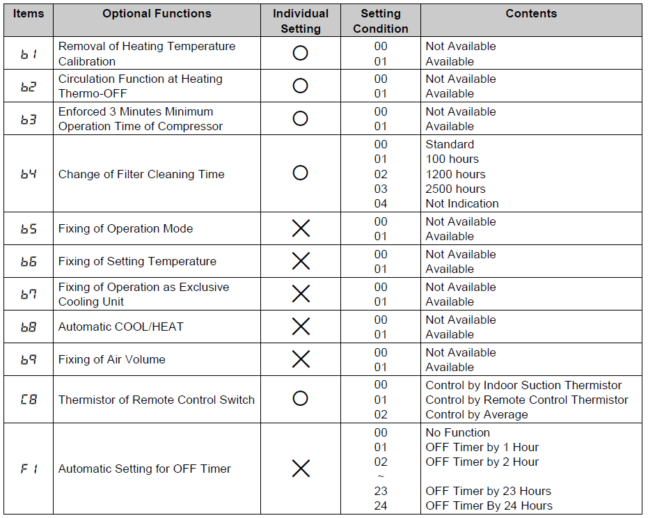
REFERENCE
DOWNLOAD MANUAL
HITACHI PC-2H2 REMOTE CONTROLLER Thermostat Installation Manual
![]()
HITACHI PC-2H2 REMOTE CONTROLLER Thermostat Installation Manual
Leave a Reply