Tekmar 519_C Radiant Thermostat
INTRODUCTION
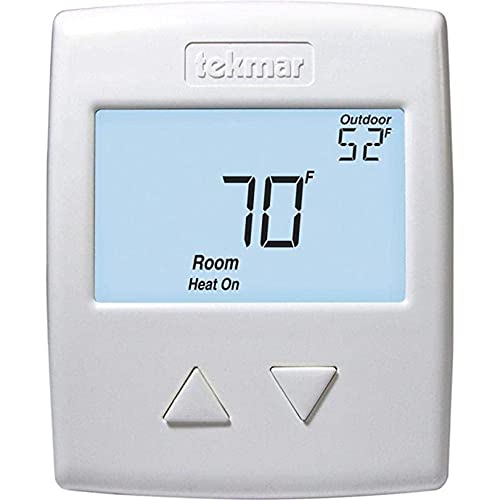
The Radiant Thermostat 519 accurately controls the room and/or floor temperature for a hydronic heating zone using Pulse Width Modulation (PWM) technology. Simple up and down buttons and a display with large type make this thermostat easy to read and use. A Slab Sensor 079 is included to measure floor temperature to protect the floor from overheating and enhance comfort. This easy to install thermostat is a direct replacement for the tekmar Thermostat 509.
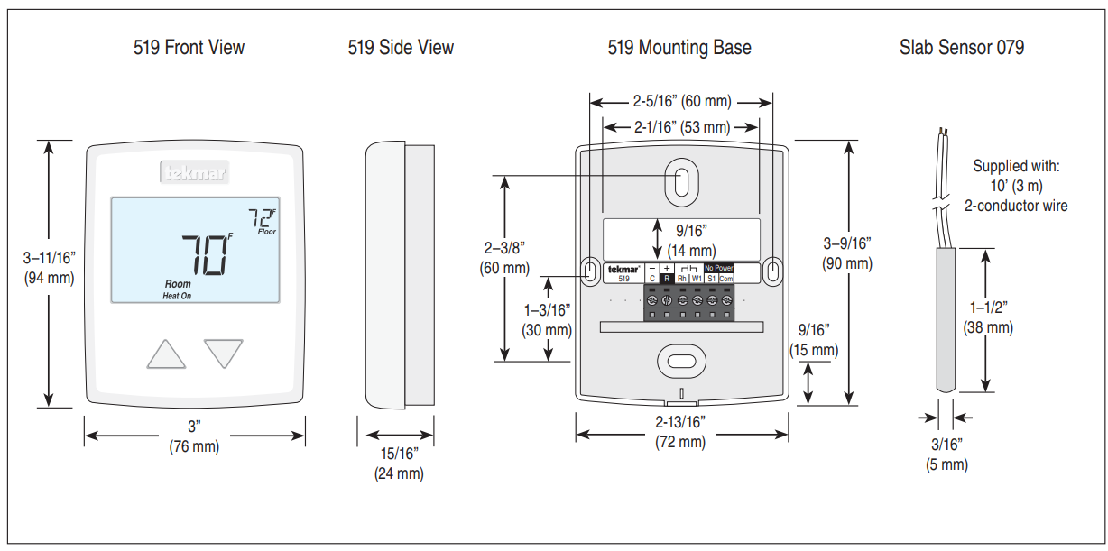
DIMENSION
Specifications
| Radiant Thermostat 519 One Stage Heat | |
| Literature | 519_C, 519_D, 519_Q, 519_U |
| Control | Microprocessor control. This is not a safety (limit) control |
| Packaged weight | 0.6 lb. (290 g) |
| Dimensions | 3-11/16” H x 3” W x 15/16” D (94 x 76 x 24 mm) |
| Enclosure | White PVC plastic, NEMA type 1 |
| Approvals | Meets Class B: ICES & FCC Part 15 |
| Ambient conditions | Indoor use only, 32 to 122°F (0 to 50°C), RH ≤90% non-condensing |
| Power supply | 10 to 30 V (ac/dc), 50/60 Hz, 1.8 VA standby, 56 VA max fully loaded, Class 2 |
| Relay | 30 V (ac/dc) 2 A, Class 2 circuits |
| Sensor | NTC thermistor, 10 kΩ @ 77°F (25°C ±0.2°C) ß=3892 |
| –Included | Slab Sensor 079 |
| –Optional | tekmar type # 070, 072, 073, 076, 077, 079, 084 |
| Warranty | Limited 3 Year (See 519_D for full warranty) |
| Slab Sensor 079 10’ (3 m) wire | |
| Dimensions | 3/16” OD x 1-1/2” (5 OD x 38 mm) |
| Enclosure | 316 stainless steel, 10’ (3 m) 24 AWG, 300 volt PVC insulated Zipcord |
| Approvals | CSA C US |
| Operating range | -58 to 140°F (-50 to 60°C) |
| Sensor | NTC thermistor, 10 kΩ @ 77°F (25°C ±0.2°C) ß=3892 |
Energy Saving Features
- Auto Heating Cycle
Additional Features
- Radiant Floor Heating
- Pulse Width Modulation
- Floor & Air Temperature Control
- Outdoor & Floor Temperature Display
- Backlight
- Freeze Protection
- Includes Slab Sensor 079
Scan code for a quick link to the product page on tekmarControls.com

Sample Application Drawing
Below is a sample application drawing for this product. This application may include other tekmar products that are required
for installation. More sample applications can be found at www.tekmarControls.com.
Sample Mechanical diagram
Legend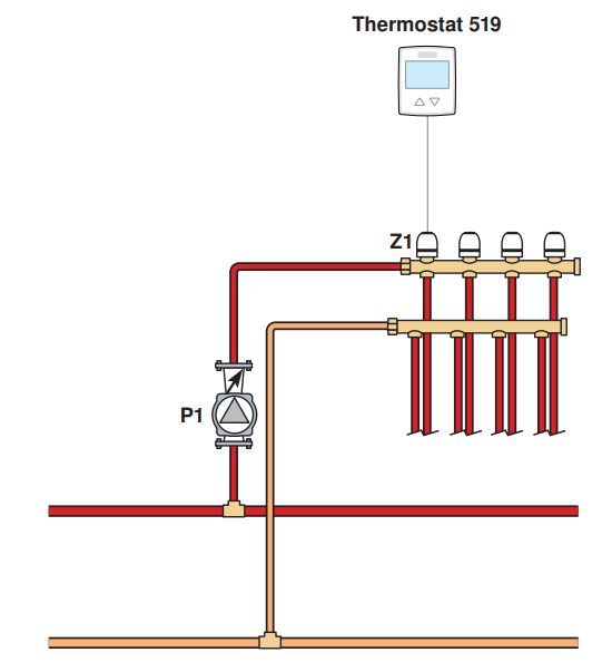
- P1 = Manifold Pump
- S1 = Optional Slab Sensor 079
- T1 = 24 V (ac) Transformer 009
- Z1 = Zone Valve
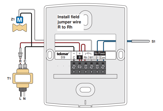
Sample Electrical Diagram
tekmar Control Systems Ltd., A Watts Water Technologies Company.
Head Office: 5100 Silver Star Road, Vernon, B.C. Canada V1B 3K4, 250-545-7749,
Fax. 250-545-0650
Web Site: www.tekmarControls.com
Product design, software and literature are Copyright ©2013 by tekmar Control Systems Ltd., A Watts Water Technologies Company
All specifications are subject to change without notice. Printed in Canada. 519_C – 03/13.
REFERENCE:
Download Manual:
Tekmar 519_C Radiant Thermostat Product Specifications Guide
![]()
Tekmar 519_C Radiant Thermostat Product Specifications Guide