
tekmar D 537 Programmable Thermostat
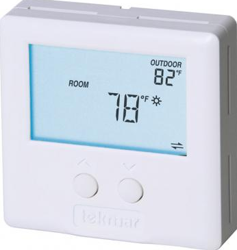
Introduction
The tekmarNet®4 Thermostat 537 provides operation for:
- One Stage Heat
Features
- Zone Synchronization
- Zone Post Purge
- Intelligent Setback (Timer 033)
- One touch overrides (User Switch)
- Auto Heating Cycle
- tekmarNet® 4 communication compatible
- Requires 4 wires
- One stage heat
- Pulse Width Modulation
- CSA C US Approved for use in USA and Canada
- Outdoor temperature display
- Air Group member
- Backlight
- Freeze Protection
- Equipment Exercising
- Room Temperature Limiting
- Supports Radiant Floor Cooling
Getting Started
Congratulations on the purchase of your new tekmar thermostat. This manual will step through the complete installation, programming and sequence of operation for this control. At the back, there are tips for control and system troubleshooting
Installation
Caution
Improper installation and operation of this control could result in damage to the equipment and possibly even personal injury or death. It is your responsibility to ensure that this control is safely installed according to all applicable codes and standards. This electronic control is not intended for use as a primary limit control. Other controls that are intended and certified as safety limits must be placed into the control circuit
Preparation
Tools Required
- tekmar or jeweller screwdriver
- Phillips head screwdriver
- Wire Stripper
Materials Required
- 2, #6 x 1” Wood Screws
- 18 AWG LVT Solid Wire
- Optional Adapter Plate 007 (for installation on 2” x 4” gang box)
Installation Location
Choose the placement of the thermostats early in the construction process to enable proper wiring during rough-in.
Consider the following:
- Interior Wall.
- Keep dry. Avoid potential leakage onto the control.
- Relative Humidity max 92% up to 104°F (40°C), 50% RH above 104°F (40°C).
- Non-condensing environment.
- No exposure to extreme temperatures beyond 32-122°F (0-50°C).
- No draft, direct sun, or other cause for inaccurate temperature readings.
- Away from equipment, appliances, or other sources of electrical interference.
- Easy access for wiring, viewing, and adjusting the display screen.
- Approximately 5 feet (1.5 m) off the finished floor.
- The maximum length of wire is 500 feet (150 m).
- Strip wire to 3/8” (10 mm) for all terminal connections.
- Use standard 4 conductor, 18 AWG wire.
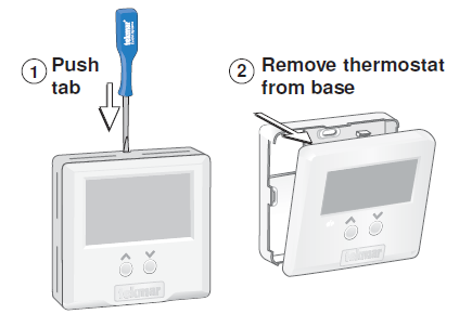
Removing The Thermostat Base
- To remove the thermostat base:
- Place a small slot screwdriver or similar tool into the slot located on the top of the thermostat.
- While pushing down against the plastic tab, pull the thermostat away from the thermostat’s base
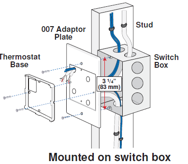
Mounting The Thermostat Base
- If a single gang switch box is used, an Adaptor Plate 007 is required to mount the thermostat to the box.
- Fasten the base of the thermostat to the adaptor plate.
- Feed the wiring through the openings in the back of the adaptor plate and thermostat.
- Use the upper and lower screw holes to fasten the adaptor plate to the box
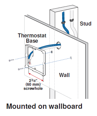
- If a switch box was not used, mount the thermostat directly to the wall.
- Feed the wiring through the openings in the back of the thermostat.
- Use screws in the screw holes to fasten the thermostat to the wall. At least one of the screws should enter a wall stud or similar rigid material
Thermostat Wiring
The thermostat operates a single heating system zone. Connect tN4, C, R, and W terminals on the thermostat to the tN4, C, R and W terminals on the tN4 Wiring Center or Zone Manager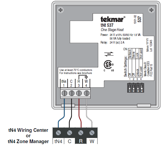
Testing the Thermostat Wiring
Testing the Power
- Remove the front cover from the thermostat.
- Use an electrical test meter to measure (ac) voltage between the R and C terminals. The reading should be 24 V (ac) +/– 10%.
- Install the front cover.
Testing the Heat Relay
- Remove the front cover from the thermostat.
- Press the
 button and set the heating temperature below the current room temperature. There should be no H1 symbol on the display.
 - Set the electrical test meter to continuity.
- Place probes between R (3) and W (4). There should be no continuity. If there is continuity then there may be a wiring fault or the relay may be faulty.
- Press the
 button and set the heating temperature above the current room temperature. Make sure the display does not show “WWSD”. The “H1” symbol should appear on the display.
 - There should be continuity between the R (3) and W (4) terminals.
Testing the tekmarNet®4 Bus
The ![]() symbol is shown on the display when communication is present. If the thermostat is connected in a network and the communication is missing, there may be an open or short circuit on the tN4 and C bus wires.
symbol is shown on the display when communication is present. If the thermostat is connected in a network and the communication is missing, there may be an open or short circuit on the tN4 and C bus wires.
- Remove the front cover from the thermostat.
- To test for short circuits:
- Disconnect the tN4 bus wires on one end.
- Install wire nuts on each wire to ensure the wire ends are not touching.
- Disconnect the tN4 bus wires on the other end.
- Measure for continuity using an electrical meter.
- If continuity is present, there is a short circuit fault along the wires. It is recommended to replace the tN4 bus wires.
To test for open circuits:
- Disconnect the tN4 bus wires on one end and connect them together.
- Disconnect the tN4 bus wires on the other end.
- Use an electrical meter to measure for continuity.
- If there is no continuity, there is an open circuit fault along the wires. It is recommended to replace the tN4 bus wires.
Mounting the Thermostat
To place the thermostat back on the mounting base: Place thermostat bottom tabs onmatching mounting base notches. Pivot top of the thermostat towards wall, ensuring wires clear obstructions. The top clasp makes a clicking sound when properly closed.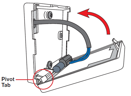
Cleaning the Thermostat
The thermostats’s exterior can be cleaned using a damp cloth. Moisten the cloth with water and wring out prior to wiping the control. Do not use solvents or cleaning solutions.
Switch Settings
Switches are set to “On” position from the factory, and do not require changing for most applications.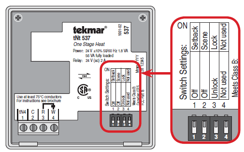
Switch Position Action
| Switch | Position | Action |
|
1 |
ON |
SETBACK
The thermostat follows a programmable setback schedule as a schedule member if available. Requires the installation of a Timer 033 to use this feature. |
|
OFF |
OFF
The thermostat does not follow a programmable setback schedule. |
|
|
2 |
ON |
SCENE
The thermostat responds to changes in the scene (system wide manual overrides). Requires the installation of a User Switch 479 to use this feature. |
| OFF | OFF
The thermostat does not respond to scenes. |
|
|
3 |
ON |
LOCK ACCESS LEVEL
Locked to ‘User’ access level. Set to Lock when installation completed. |
|
OFF |
UNLOCK ACCESS LEVEL
Unlock to allow ‘User’ and “Installer’ access level. Set to Unlock during installation process. tekmarNet® reset control must also be set to Unlocked (Installer access level). |
|
|
4 |
ON | Not used |
| OFF | Not used |
User Interface
Display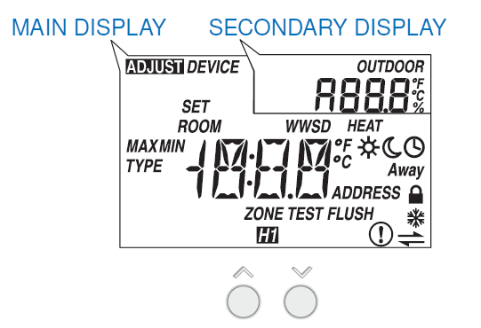
Button Operation
Press the ![]() the button to select the room temperature
the button to select the room temperature
Symbols Description
| HEAT
Heat is turned on. |
LOCK
Locked to ‘User’ access level. |
| SUN
Operating at the occupied (day) temperature. |
CLOCK
Operating on a programmable schedule. |
| MOON
Operating at the unoccupied (night) temperature. |
tekmarNet®
Communication is present. |
| AWAY
Operating at the Away scene temperature. |
WARNING SYMBOL
Indicates an error is present. |
| AIR GROUP
The air group is cooling. Heating can start once the cooling is finished. |
WARM WEATHER SHUT DOWN
The heating system has been shut off for the summer. |
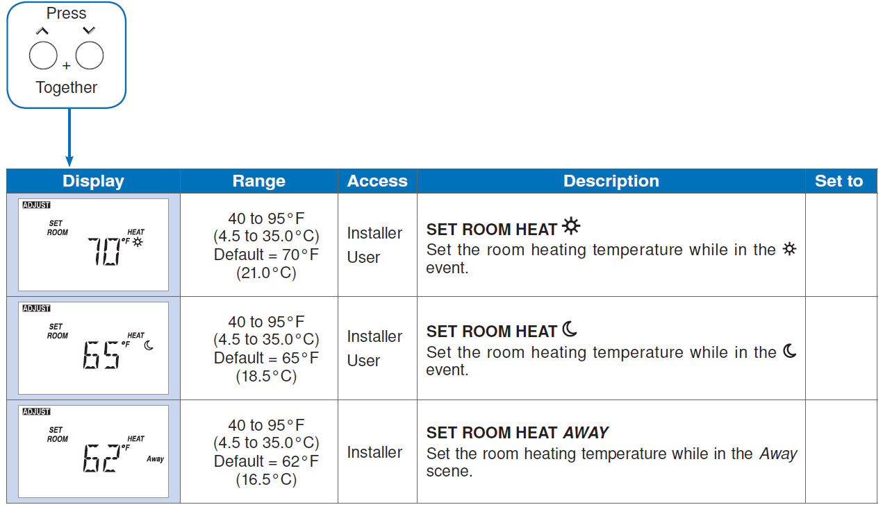
Settings (1 of 5)
- Press and hold down both the and buttons for 2 seconds to change from one step to the next.
- Release both buttons once the step has been reached.
- Press the or the button to change the setting, if available.
- Press and hold down both the and buttons for 2 seconds to go to the next step, OR
- After 10 seconds of no button activity, the display goes back to normal operation.
- Note: Set switch setting #3 and tekmarNet® system control to Unlock to change Access level to Installer
Settings ( 2 of 5)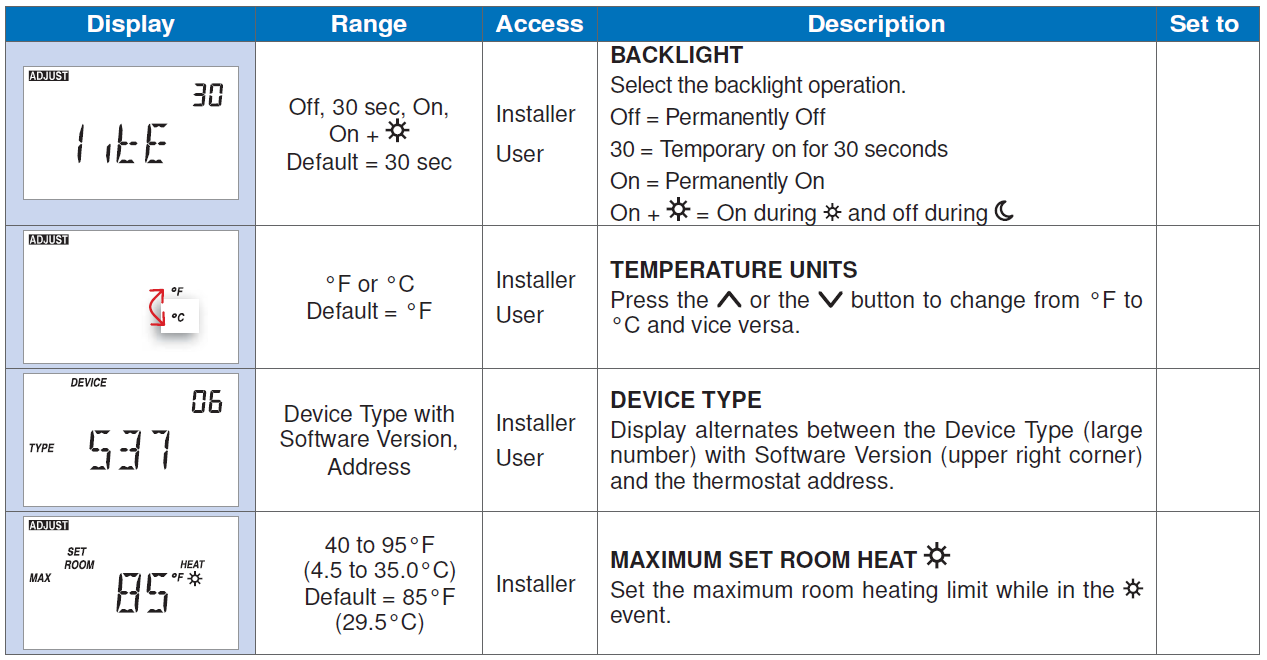
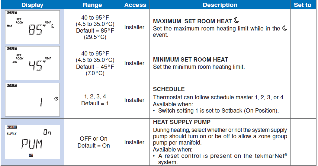
Settings (3 of 5)
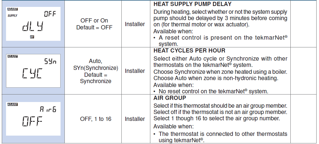
Settings (4 of 5)
Settings (5 of 5)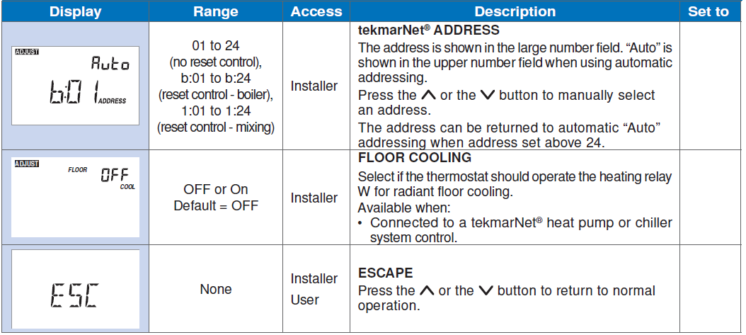
Sequence of Operation
Heating Operation Section A
The thermostat operates the heating system to maintain the Set Room Heat temperature. An H1 symbol is shown on the display when the thermostat is heating. The heat can cycle on and off within +/- 1.5°F (1°C) of the Set Room Heat temperature.
Freeze Protection
The thermostat operates the heat whenever the room temperature falls below 40°F (4.5°C).
Exercising
When connected to a tekmarNet® reset control, the thermostat exercises the heat relay for 10 seconds every 3 days. Exercising helps prevent zone valves or zone pumps from failing due to precipitate buildup. During exercising, the thermostat shows “TEST” on the display.
Flushing
The flushing feature is for open-loop systems that use a domestic hot water tank as a heat source. Flushing ensures that fresh potable water is circulated through the system once each day. If the thermostat is connected to a tekmarNet® reset control with the Flushing feature turned on, the thermostat display will display the “FLUSH” icon for the duration of the flushing operation.
Hydronic System Supply Pump
When connected to a tekmarNet® system control, the thermostat’s Heat Supply Pump setting affects how the primary pump or mix pump on the system control operates. When connected to the boiler bus, the boiler system or primary pump is operated. When connected to the mix bus, the mix system pump is operated. If the thermostat operates a motorized or thermal motor zone valve, the Heat Supply
Pump setting should be set to On.
If the thermostat operates a thermal motor (wax actuator) zone valve, set the Heat Supply Pump Delay setting to On. This provides a three minute delay to allow the zone valve to open before the primary or mix pump is turned on. In special applications with multiple zoning manifolds, the Heat Supply Pump setting can be set to Off. This allows a Zone Group Pump located on the Zone Manager, or Wiring Center to operate the pump for the manifold.
DHW Tank Priority
When a tekmarNet® reset control is heating an indirect Domestic Hot Water (DHW) tank, the thermostat may shut off the heating zones to allow the DHW tank to recover quickly. This is determined by the DHW priority of the tekmarNet® reset control.
Warm Weather Shut Down
When the outdoor air temperature exceeds the Warm Weather Shut Down (WWSD) setting on the tekmarNet® reset control, the heating system is shut off.
Air Group Operation Section B
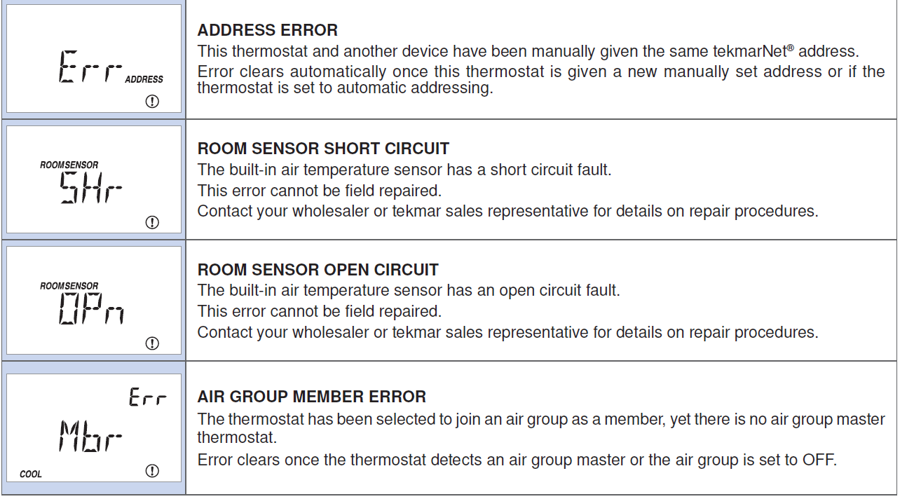
In order to prevent heating and cooling at the same time, this thermostat can operate together with other thermostats on a tekmarNet® system to form an air group. In an air group, one thermostat is assigned as the air group master. The air group master operates the cooling equipment for the group. This thermostat can be set to be a member of the air group. When operating as an air group, the air temperature readings of all the air group member thermostats are communicated to the air group master and a temperature average is determined. When the air group master is in cooling operation, the air group member thermostats do not operate the heating system for air heating. If the Set Room Heat temperature is adjusted while the air group is cooling, the snowflake icon is flashed to alert the user that the cooling is presently on. Once the cooling shuts off, the heating can start operation.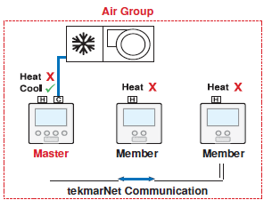
Floor Cooling Section C
The thermostat has the option to support radiant floor cooling when connected to a heat pump control using tekmarNet® communication. The floor cooling setting must be set to On and the heating system must be in Warm Weather Shut Down (WWSD). When the heat pump system control operates in cooling mode, all thermostats set for floor cooling on the tekmarNet® bus all activate the first stage heating contact (H1) at the same time to allow chilled water into the system. The thermostat continues to operate the cooling until either the room temperature reaches the Set Heat temperature plus 3°F (Set Heat+1.5°C) or reaches a minimum temperature of 74°F. If only a floor sensor is installed, the floor cooling setpoint is 67°F (19.5°C
Schedules Section D
Lowering the room temperature setting reduces the amount of fuel required to heat the building resulting in energy savings. This thermostat can follow a programmable schedule in order to automatically lower the room temperature setting. A schedule master such as a Timer 033 is required in order to gain programmable schedule functionality. When operating on a programmable schedule, a symbol is shown, as well as a
 or
or a . The or indicates the current operating temperature. If a symbol does not appear, there is no schedule available.
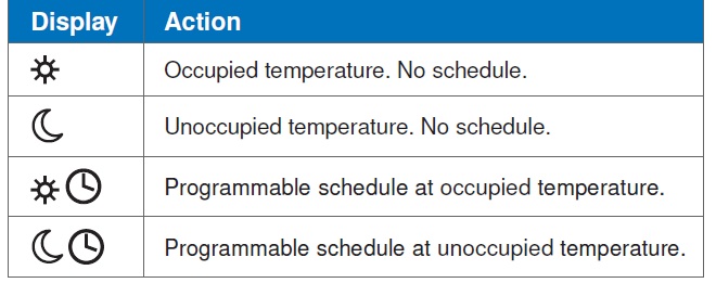
Scenes (System Override)
Scenes provide an easy way to save energy while away on vacation, or override a pre-set schedule when plans change. tekmarNet® devices such as a User Switch 479 provide scene adjustment. This thermostat responds to the following scenes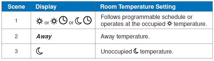
Troubleshooting
Error Messages (1 of 2)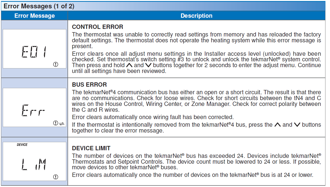
Error Messages ( 2 of 2)
Frequently Asked Questions
| Frequently Asked Questions | ||
| Symptom | Look for… | Corrective Action |
|
No Heat |
H1 Symbol | H1 symbol indicates heat is on. Check if zone valve or zone pump is operating. |
| Flashing WWSD | Increase WWSD setting on tekmarNet® reset control. | |
| Flashing Away | Change User Switch to Normal scene 1. | |
|
Heat on before scheduled time |
|
Optimum start “learns” the heat up rate of the room and starts the heating early so that the room is comfortable at the scheduled time. |
| Pressing | ||
| button does not increase temperature | Flashing Max | Installer can increase the Maximum Set Room Heat limits. |
| Pressing | ||
| button does not decrease temperature | Flashing Min | Installer can decrease the Minimum Set Room Heat limits. |
Job Record
| Item | Setting | Item | Setting |
| Set Room Heat | Schedule Member | ||
| Set Room Heat | Heat Supply Pump | ||
| Set Room Heat Away | Heat Supply Pump Delay | ||
| Backlight | Heat Cycles Per Hour | ||
| Units | Air Group | ||
| Max Set Room Heat | tekmarNet® Address | ||
| Max Set Room Heat | Floor Cooling | ||
| Min Set Room Heat | |||
Technical Data
| tekmarNet®4 Thermostat 537; One Stage Heat | |
| Packaged weight | 0.8 lb. (380 g) |
| Enclosure | White PVC plastic, NEMA Type 1 |
| Dimensions | 2-7/8” H x 2-7/8” W x 13/16” D (73 x 73 x 21 mm) |
| Approvals | CSA C US, meets Class B: ICES and FCC Part 15 |
| Ambient conditions | Indoor use only, 32 to 122°F (0 to 50°C). |
| RH max 92% to 104°F (40°C), and 50% above 104°F (40°C) | |
| Altitude <9840 feet (3000 m), Installation Category II, Pollution Degree 2 | |
| Power supply | 24 V (ac) ± 10% 50/60 Hz, 1.8 VA Standby, 56 VA fully loaded, NEC / CEC Class 2 |
| W Relay | 24 V (ac) 2 A |
Warranty
Limited Warranty and Product Return Procedure
Limited Warranty The liability of tekmar under this warranty is limited. The Purchaser, by taking receipt of any tekmar product (“Product”), acknowledges the terms of the Limited Warranty in effect at the time of such Product sale and acknowledges that it has read and understands same. The tekmar Limited Warranty to the Purchaser on the Products sold hereunder is a manufacturer’s passthrough warranty which the Purchaser is authorized to pass through to its customers. Under the Limited Warranty, each tekmar Product is warranted against defects in workmanship and materials if the Product is installed and used in compliance with tekmar’s instructions, ordinary wear and tear excepted. The pass-through warranty period is for a period of twenty-four (24) months from the production date if the Product is not installed during that period, or twelve (12) months from the documented date of installation if installed within twenty-four (24) months from the production date.
The liability of tekmar under the Limited Warranty shall be limited to, at tekmar’s sole discretion: the cost of parts and labor provided by tekmar to repair defects in materials and/or workmanship of the defective product; or to the exchange of the defective product for a warranty replacement product; or to the granting of credit limited to the original cost of the defective product, and such repair, exchange or credit shall be the sole remedy available from tekmar, and, without limiting the foregoing in any way, tekmar is not responsible, in contract, tort or strict product liability, for any other losses, costs, expenses, inconveniences, or damages, whether direct, indirect, special, secondary, incidental or consequential, arising from ownership or use of the product, or from defects in workmanship or materials, including any liability for fundamental breach of contract. The pass-through Limited Warranty applies only to those defective Products returned to tekmar during the warranty period.
This Limited Warranty does not cover the cost of the parts or labor to remove or transport the defective Product, or to reinstall the repaired or replacement Product, all such costs and expenses being subject to Purchaser’s agreement and warranty with its customers Any representations or warranties about the Products made by Purchaser to its customers which are different from or in excess of the tekmar Limited Warranty are the Purchaser’s sole responsibility and obligation. Purchaser shall indemnify and hold tekmar harmless from and against any and all claims, liabilities and damages of any kind or nature which arise out of or are related to any such representations or warranties by Purchaser to its customers.
The pass-through Limited Warranty does not apply if the returned Product has been damaged by negligence by persons other than tekmar, accident, fire, Act of God, abuse or misuse; or has been damaged by modifications, alterations or attachments made subsequent to purchase which have not been authorized by tekmar; or if the Product was not installed in compliance with tekmar’s instructions and / or the local codes and ordinances; or if due to defective installation of the Product; or if the Product was not used in compliance with tekmar’s instructions. THIS WARRANTY IS IN LIEU OF ALL OTHER WARRANTIES, EXPRESS OR IMPLIED, WHICH THE GOVERNING LAW ALLOWS PARTIES TO CONTRACTUALLY EXCLUDE, INCLUDING, WITHOUT LIMITATION, IMPLIED WARRANTIES OF MERCHANTABILITY AND FITNESS FOR A PARTICULAR PURPOSE, DURABILITY OR DESCRIPTION OF THE PRODUCT, ITS NON-INFRINGEMENT OF ANY RELEVANT PATENTS OR TRADEMARKS, AND ITS COMPLIANCE WITH OR NON-VIOLATION OF ANY APPLICABLE ENVIRONMENTAL, HEALTH OR SAFETY LEGISLATION; THE TERM OF ANY OTHER WARRANTY NOT HEREBY CONTRACTUALLY EXCLUDED IS LIMITED SUCH THAT IT SHALL NOT EXTEND BEYOND TWENTY-FOUR (24) MONTHS FROM THE PRODUCTION DATE, TO THE EXTENT THAT SUCH LIMITATION IS ALLOWED BY THE GOVERNING LAW.
Product Warranty Return Procedure All Products that are believed to have defects in workmanship or materials must be returned, together with a written description of the defect, to the tekmar Representative assigned to the territory in which such Product is located. If tekmar receives an inquiry from someone other than a tekmar Representative, including an inquiry from Purchaser (if not a tekmar Representative) or Purchaser’s customers, regarding a potential warranty claim, tekmar’s sole obligation shall be to provide the address and other contact information regarding the appropriate Representative
tekmar
- tekmar Control Systems Ltd., Canada
- tekmar Control Systems, Inc., U.S.A.
- Head Office: 5100 Silver Star Road
- Vernon, B.C. Canada V1B 3K4
- (250) 545-7749 Fax. (250) 545-0650
- Web Site: www.tekmarcontrols.com
Reference:
Download manuals:
tekmar D 537 programmable Thermostat Operational Manual
Leave a Reply