
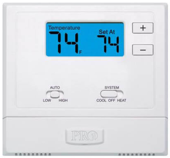
Pro1 Technologies T801 Non-Programmable Thermostat
Pro1 Technologies
P.O. Box 3377
Springfield, MO 65808-3377
Toll-Free: 888-776-1427
Web: www.pro1iaq.com
Hours of Operation: M-F 9 AM – 6 PM Eastern
Thermostat Application Guide
| Description | |
| Gas or Oil Heat | Yes |
| Electric Furnace | Yes |
| Heat Pump (No Aux. or Emergency Heat) | Yes |
| Heat Pump (With Aux. or Emergency Heat) | No |
| Multi-Stage Systems | No |
| Heat Only Systems | Yes |
| Cool Only Systems | Yes |
| Millivolt | Yes |
Power Type
- Battery Power
- Hardwire (Common Wire)
- Hardwire (Common Wire) with Battery
- Backup
A trained, experienced technician must install this product. Carefully read these instructions. You could damage this product or cause a hazardous condition if you fail to follow these instructions.
Installation Tips
Wall Locations
The thermostat should be installed approximately 4 to 5 feet above the floor. Select an area with average temperature and good air circulation.
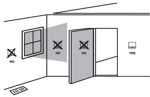
Pick an installation location that is easy for the user to access. The temperature of the location should be representative of the building.
Subbase Installation
- Horizontal Mount
- Vertical Mount
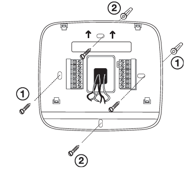
For vertical mount put one screw on the top and one screw on the bottom. For horizontal mount put one screw on the left and one screw on the right.
Do not install the thermostat in locations:
- Close to hot or cold air ducts
- That is in direct sunlight
- With an outside wall behind the thermostat
- In areas that do not require conditioning
- Where there are dead spots or drafts (in corners or behind doors)
- Where there might be concealed chimneys or pipes
Installation Tip:
Electrical Hazard
Failure to disconnect the power before beginning to install this product can cause electrical shock or equipment damage.
Mercury Notice
All of our products are mercury-free. However, if the product you are replacing contains mercury, dispose of it properly. Your local waste management authority can give you instructions on recycling and proper disposal.
Thermostat Quick Reference
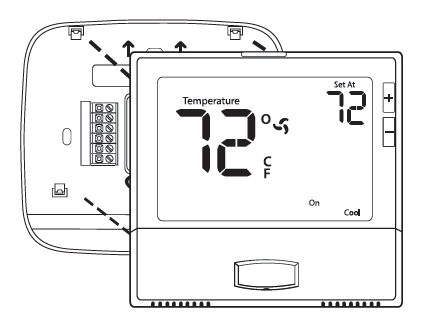
Mount Thermostat
Align the 4 tabs on the subbase with corresponding slots on the back of the thermostat, then push gently until the thermostat snaps in place.
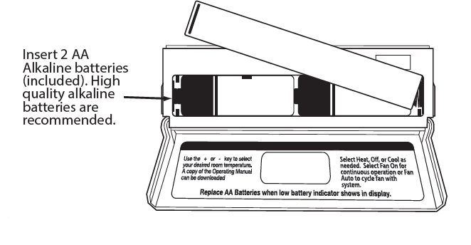
Battery Installation
Important:
High-quality alkaline batteries are recommended. Rechargeable batteries or low-quality batteries do not guarantee a 1-year life span.
Getting to know your thermostat
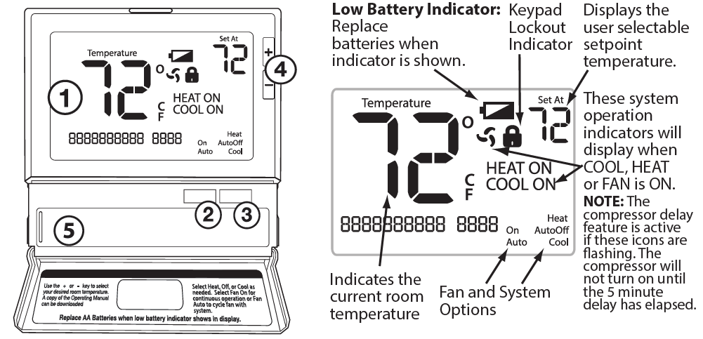
- LCD
- Fan Button
- System Button
- Setpoint Buttons
- Battery Cover
Removing The Private Label Badge
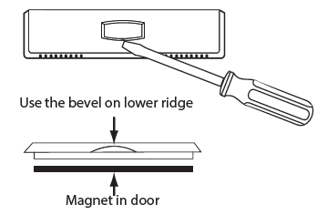
About The Badge
All of our thermostats use the same universal magnetic badge. Visit the company website to learn more about our free private label program.
Important
The low battery indicator is displayed when the AA battery power is low. If the user fails to replace the battery within 21 days, the screen will only show the low battery indicator but maintain all functionality. If the user fails to replace the batteries after an additional 21 days (days 22-42 since the first “low battery” display) the setpoints will change to 55˚F (Heating) and 85˚F (Cooling). If the user adjusts the setpoint away from either of these, it will hold for 4 hours and then return to either 55˚F or 85˚F. After day 63 the batteries must be replaced immediately to avoid freezing or overheating because the thermostat will shut the unit off until the batteries are changed. Gently slide a screwdriver into the bottom edge of the badge. Gently turn the screwdriver counterclockwise. The badge is held on by a magnet in the well of the battery door. The badge should pry off easily. DO NOT USE FORCE.
Wiring
- If you are replacing a thermostat, make note of the terminal connections on the thermostat that is being replaced. In some cases, the wiring connections will not be color coded. For example, the green wire may not be connected to the G terminal.
- Loosen the terminal block screws. Insert wires then retighten terminal block screws.
- Place non-flammable insulation into the wall opening to prevent drafts.
Terminal Designations
- C Heat pump changeover valve energized in cooling
- Heat pump changeover valve energized in heating
- W Heat relay
- RH Transformer power for heating
- RC Transformer power for cooling
- G Fan relay
- Y Compressor relay
- B Common wire from the secondary side of the cooling system transformer
Caution: Electrical Hazard Failure to disconnect the power before beginning to install this product can cause electrical shock or equipment damage.
Warning: All components of the control system and the thermostat installation must conform to Class II circuits per the NEC Code.
RH & RC Terminals
For single transformer systems, leave the jumper wire in place between RH and RC. Remove the jumper wire for the two transformer systems.
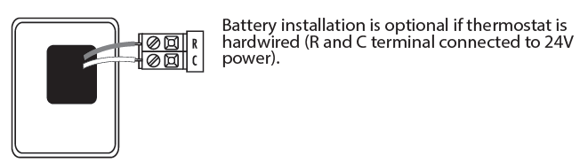
C Terminal
The C (common wire) terminal does not have to be connected when the thermostat is powered by batteries.
Wire Specifications
Use shielded or non-shielded 18-22 gauge thermostat wire.
Installation Tip: Do not overtighten terminal block screws, as this can damage the terminal block. A damaged terminal block can keep the thermostat from fitting on the sub-base correctly or cause system operation issues. Max Torque = 6in-lbs.
Heat Pump Systems
If wiring to a heat pump, use a small piece of wire (not supplied) to connect terminals W and Y.
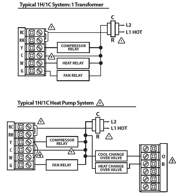
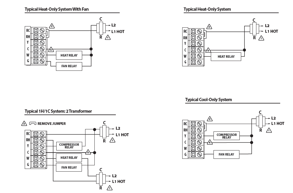
Wiring Diagrams
- Power supply
- Factory-installed jumper. Remove only when installing on 2-transformer systems.
- Use either O or B terminals for the changeover valve.
- Use a small piece of wire (not supplied) to connect W and Y terminals.
- Set the fan operation switch to electric.
- Optional 24 VAC common connection when the thermostat is used in battery power mode.
Technician Setup
- To enter Tech Setup Menu, press and hold and together for 3 seconds.
- Use
 or
or  select the desired setting for each option.
 - Use the System and Fan buttons to move through the steps.
- To exit Tech Setup press and hold together for 3 seconds.
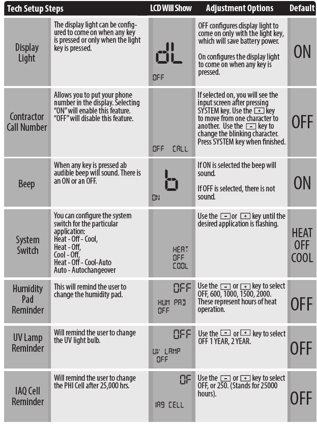
|
Filter Change Reminder |
This feature will flash “a reminder” in the display after the elapsed run time to remind the user to change the filter. A setting of “OFF” will disable this feature. | SE
F1 OFF |
You can adjust the filter change reminder from OFF to 2000 hours of runtime in 50 hour increments. | 0FF | |
|
Room Temperature Calibration |
This feature allows the installer to change the calibration of the room temperature display. For example, if the thermostat reads 70˚ degrees and you would like it to read 72˚ then select +2. | 0 | You can adjust the room temperature display to read 4˚above or below the factory calibrated reading. | 0 | |
|
Minimum Compressor On Time |
This feature allows the installer to select the minimum run time for the compressor. For example: a setting of 4 will force the compressor to run for at least 4 minutes every time the compressor turns on, regardless of the room temperature. |
A OFF |
You can select the minimum compressor run time from “off”, “3”, “4”, or “5” minutes. If 3,4, or 5 is selected, the compressor
will run for at least the selected time before turning off. |
0FF |
|
|
Compressor Short Cycle Delay |
The compressor short cycle delay protects the compressor from short cycling. This feature will not allow the compressor to be turned on for 5 minutes after it was last turned off. | OF
CO
|
Selecting “ON” will not allow the compressor to be turned on for 5 minutes after the last time the compressor was switched off. Select “OFF” to remove this delay. | 0N | |
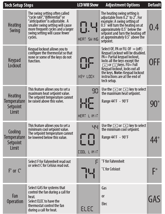
|
Cooling Swing |
The swing setting often called “cycle rate”, “differential” or “ anticipation” is adjustable. A smaller swing setting will cause more frequent cycles and a larger swing setting will cause fewer cycles. | 0.5
COOL SWING |
The cooling swing setting is adjustable from 0.2˚ to 2˚. For example: A swing setting of 0.5˚ will turn the cooling on at approximately 0.5˚ above the setpoint and turn the cooling off at approximately 0.5˚ below the setpoint. |
0.5 |
Wiring Diagrams
Technician Setup & Specifications
Once a reminder has been turned on and set, the elapsed time can be checked by navigating to it’s Technical Setup step with a press of the SYSTEM BUTTON, the elapsed time will be displayed. It can also be reset at the time by a press and hold of the FAN BUTTON for 3 seconds. Resetting an expired reminder can be done without entering the tech setup, by a press and hold of the FAN BUTTON for 3 seconds.
A Note About Keypad Lockout
The function of activating your lockout choice takes place after you have exited the tech setup to lock or unlock the keypad and hold down the FAN and SYSTEM for 3 seconds.
Specifications
- The display range of temperature … 41˚F to 95˚F (5˚C to 35˚C)
- The control range of temperature… 44˚F to 90˚F (7˚C to 32˚C)
- Load rating………………………………………….1 amp per terminal, 1.5 amp maximum for all terminals combined
- Swing (cycle rate or differential) …… The heating is adjustable from 0.2˚ to 2.0˚
- Cooling is adjustable from 0.2˚ to 2.0˚
- Power source …………………………………….18 to 30 VAC, NEC Class II, 50/60 Hz for hardwire
- Battery power from 2 AA Alkaline batteries
- Operating ambient …………………………. 32˚F to +105˚F (0˚C to +41˚C)
- Operating humidity ………………………… 90% non-condensing maximum
- Dimensions of thermostat …………….. 4.7”W x 4.4”H x 1”D
Reference
Download Manual:
Pro1 Technologies T801 Non-Programmable Thermostat Installational Manual
OTHER MANUALS
Pro1 Technologies T801 Non-Programmable Thermostat Operational Manual
Pro1 Technologies T801 Non-Programmable Thermostat Product Specifications Guide
![]()
Pro1 Technologies T801 Non-Programmable Thermostat Installation Manual
Leave a Reply