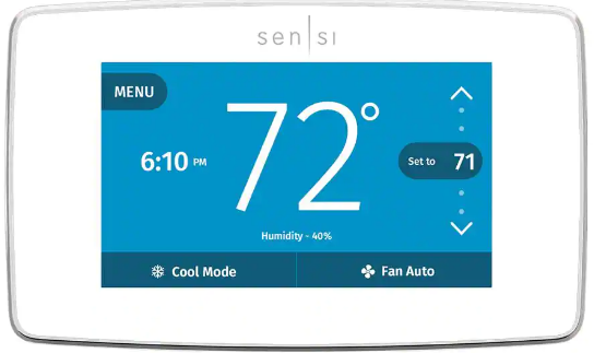
EMERSON ST75W Sensi Touch Wi-Fi Smart Thermostat
What’s in the box?
- Sensi Thermostat
- Screws and Anchors
- Wire Labels
Items needed for Wi-Fi connection
- The homeowners compatible iOS or Android
- Device with the Sensi app installed and registered
- Your customer’s Wi-Fi network name (SSID) and password
- A Wi-Fi network with 802.11n 2.4GHz band
Installation
- Turn terminal light switch on for better visibility.
- install Sensi thermostat, referring to these terminal definitions, cross references and wiring diagrams as needed
|
OLD THERMOSTAT |
SENSI THERMOSTAT |
CONVENTIONAL HEAT PUMP SYSTEM SYSTEM |
| RH | RH* | Power for heating, 24V |
| RC, R | RC* | Power for cooling, 24V |
| C, X, B** | C | Common wire, 24V |
|
Y, Y1 |
Y |
1st stage cool 1st outdoor stage heat |
|
Y2 |
Y2/* |
2nd stage cool 2nd outdoor stage
heat and cool |
Designed by the pros for the pros
There are a lot of choices when it comes to buying a thermostat, but only one combines 125 years of experience and the latest connected home technology to empower your customers to take control of their comfort from anywhere. We proudly connect you to a professional-grade thermostat that you can offer your customers with confidence and that will keep you connected with them even after the initial install.
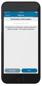
Sensi partner program
Always be the Contractor-On-Call with your customers. The Sensi app saves your contact information so when your customer needs service, you’re just a tap away. Register at www.sensiregistration.com.
Easy to install and connect
Sensi is designed to install like a standard thermostat. It gives you the flexibility to connect to Wi-Fi at installation or let your customer connect it later using the Sensi app.
MOBILE DEVICE COMPATIBILITY
| OPERATING | SYSTEM | COMPATIBILITY |
| iOS | Yes | |
SMART HOME PLATFORM COMPATIBILITY
| OPERATING | SYSTEM | COMPATIBILITY |
| Wink | Yes | |
HVAC SYSTEM COMPATIBILITY
| SYSTEM TYPE | COMPATIBILITY | MODIFICATIONS |
| Conventional heating and cooling
• Gas furnace • Air conditioner • Electric furnace • Boiler |
Yes | Requires a common wire (c-wire) |
| Heat only
• Gas furnace • Boiler |
Yes | Requires a common wire (c-wire) |
| Cool only
• Air conditioner |
Yes | Requires a common wire (c-wire) |
| Heat pump | Yes | Requires a common wire (c-wire) |
| Communicating | No | Needs standard HVAC wiring |
| Line voltage | No | Requires low voltage (20-30VAC) |
| Millivolt systems | No | Requires 20-30VAC |
SINGLE-STAGE OR MULTISTAGE SYSTEM NO HEAT PUMP WITH TWO TRANSFORMERS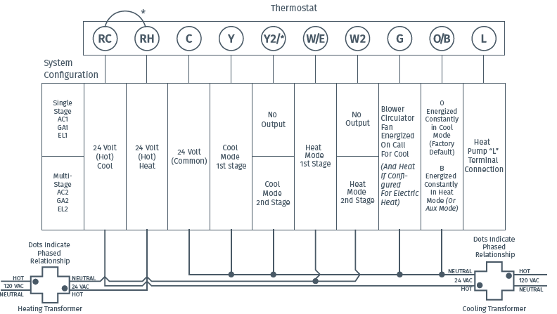
HEAT PUMP SYSTEMS 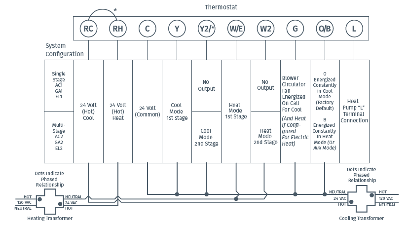
Configuration
- Before configuring the thermostat, switch off the terminal light.
- Configure the thermostat to the appropriate system type. Press “Menu” on the thermostat and refer to these menu options as needed
- Once the thermostat is installed and properly configured, test the equipment by following these steps
| No. | Menu item | Default | Options |
| 1 | Screen Brightness | Off | Adjust resting state brightness with an option to turn off |
| 2 | Backglow | Off | Off / On |
| 3 | Home Screen Content | On | Indoor Humidity |
| On | Time of Day | ||
| °F | °F / °C | ||
| 4 | Schedule | – | 5 / 2 Day Schedule |
| 5 | Wi-Fi | O | Connect to Wi-Fi |
| 6 | Time Setup | – | Set the date and time |
| 7 | About Thermostat | – | Model Number/Reset |
| 8 | Advanced Setup | HVAC Equipment | Fan Mode Options | |
| 8a | HVAC Equipment | AC2 / EL2 | |
| AC2 | Outdoor Setup AC1/AC2/HP1/HP2/AC0 | ||
| Indoor Setup GA1/GA2/EL1/EL2/Fan | |||
| EL2 | Reversing Valve Position O/B/3 | ||
| O | |||
| 8b | Fan Mode Options | ||
| Circulating Fan | Off | Off – 100% (5% increments) |
Fan Operation
- If your system does not have a “G” terminal connection, skip to “Heating System” below.
- press the “Fan” button on the thermostat and select the “On” position. The blower should begin to operate.
- Press the “Mode” button to turn off the system. Then press the “Fan” button on the thermostat and select the “Auto” position. The blower should stop immediately.
Circulating Fan
- Press the “Menu” button on the thermostat and select “Advanced Setup” then select “Fan Mode Options”
- Press “On” to enable circulating fan and set the % run time from 10%-100% in 5% increments (default is OFF).
- The % run time is the percentage of time the fan shall run in a day. This calculation takes into account the amount of time the heating, cooling and continuous fan have run during the same day.
Heating System
- Press the “Mode” button on the thermostat and select the “Heat” position.
- Press the up arrow on the thermostat and adjust the setting to 1° above the current room temperature. The heating system should begin to operate and the thermostat display will turn red indicating heating on the screen.
- For heat pumps with auxiliary, press the up arrow on the thermostat and adjust the setting to 3° above the current room temperature. The auxiliary heat should begin to operate and the thermostat will indicate “Heating Auxiliary” on the screen.
- Press the down arrow on the thermostat and adjust the setting to 1° below the current room temperature. The heating system should stop operating and the display will go back to a neutral gray color.
Auxiliary System (only for heat pumps with auxiliary)
- Press the “Mode” button on the thermostat and select the “Aux” position. This bypasses the heat pump and runs auxiliary-only heat.
- Press the up arrow on the thermostat and adjust the setting to 1° above the current room temperature. The auxiliary heating system should begin to operate and the thermostat will indicate “Heating Auxiliary” on the screen.
- Press the down arrow on the thermostat and adjust the setting to 1° below the current room temperature. The auxiliary heating system should stop operating and “Heating Auxiliary” will disappear from the screen
Cooling System
- Press the “Mode” button on the thermostat and select the “Cool” position.
- Press the down arrow and adjust the setting to 1° below the current room temperature. The blower should come on immediately on high speed, followed by cold air circulation. The thermostat display will turn blue. Note that there can be up to a 5 minute delay for this process. This is indicated by a flashing setpoint temperature.
- press the up arrow and adjust the setting to 1° above the current room temperature. The cooling system should stop operating and the display will go to a neutral gray color.
- If you encounter any issues while testing the equipment, refer to the troubleshooting actions on page 14.
Troubleshooting
| SYMPTOM | POSSIBLE CAUSE | CORRECTIVE ACTION |
| No Heat/ No Cool/ No Fan (common problem) | 1. Blown fuse or tripped circuit breaker
2. Furnace power switch to OFF 3. Furnace blower compartment door panel loose 4. Loose connection to thermostat or system |
1. Replace fuse or reset breaker
2. Turn switch to ON 3. Replace door panel in proper position to engage safety interlock or door switch 4. Tighten connections |
| SYMPTOM | POSSIBLE CAUSE | CORRECTIVE ACTION |
| No Cool | 1. Thermostat not set to Cool
2. Loose connection to thermostat or system 3. Cooling system requires service or thermostat requires replacement |
1. Set thermostat to Cool.
2. Verify thermostat and system wires are securely attached. 3. Diagnostic: Set Mode to Cool and lower setpoint below room temperature. Same procedures as diagnostic for “No Heat” condition except set the thermostat to Cool and lower the setpoint below the room temperature. There may be up to a five minute delay before the thermostat clicks in Cooling if the AC Protection feature is on. |
Connecting Sensi to Wi-Fi
- Ask the homeowner to download the free Sensi app onto the their iOS or Android device

- Ask the homeowner to follow the prompts to create an account.
- Once the homeowner has logged in, ask to use their device to connect the thermostat to the Wi-Fi.
- Select “Connect Thermostat to Wi- Fi” and follow the in-app prompts to complete the connection steps.
- Once the thermostat is connected to Wi-Fi, enter your registered phone number by selecting “Settings”, at the bottom then “Contractor Info”.
Warnings
- On two transformer systems, the transformers MUST be in phase.
- Measure the voltage across RC and RH. If more than 12 Volts AC is present between RC and RH, then the transformers are NOT in phase.
- To correct this condition, reverse the secondary low voltage connections at either the Heating or Cooling transformer.
VOLTAGE REQUIREMENTS
- Do not use on circuits exceeding specified voltage. Higher voltage will damage control and could cause shock or fire hazard.
- Thermostat installation and all components of the control system shall conform to Class II circuits per the NEC
For Your Customer
- MAKE SURE TO LEAVE THE SENSI WELCOME GUIDE FOR YOUR CUSTOMER.
- It provides helpful instructions and information on the following:
- How to connect their Sensi thermostat to Wi-Fi (if this has not already been completed) or connect additional devices
- Key features of the thermostat and the app and how they work
- Customer Support code.
Need help?
Visit sensicomfort.com/support for around-the-clock access to support articles, instructional downloads and comprehensive support videos. Our highly-trained Sensi Support Team is available seven days a week.
- 1.888.605.7131
- [email protected]
Reference
Download Manual:
EMERSON ST75W Sensi Touch Wi-Fi Smart Thermostat Installation Mnaual
OTHER MANUALS
EMERSON ST75W Sensi Touch Wi-Fi Smart Thermostat User Manual
EMERSON ST75W Sensi Touch Wi-Fi Smart Thermostat User Guide
![]()
EMERSON ST75W Sensi Touch Wi-Fi Smart Thermostat Installation Manual