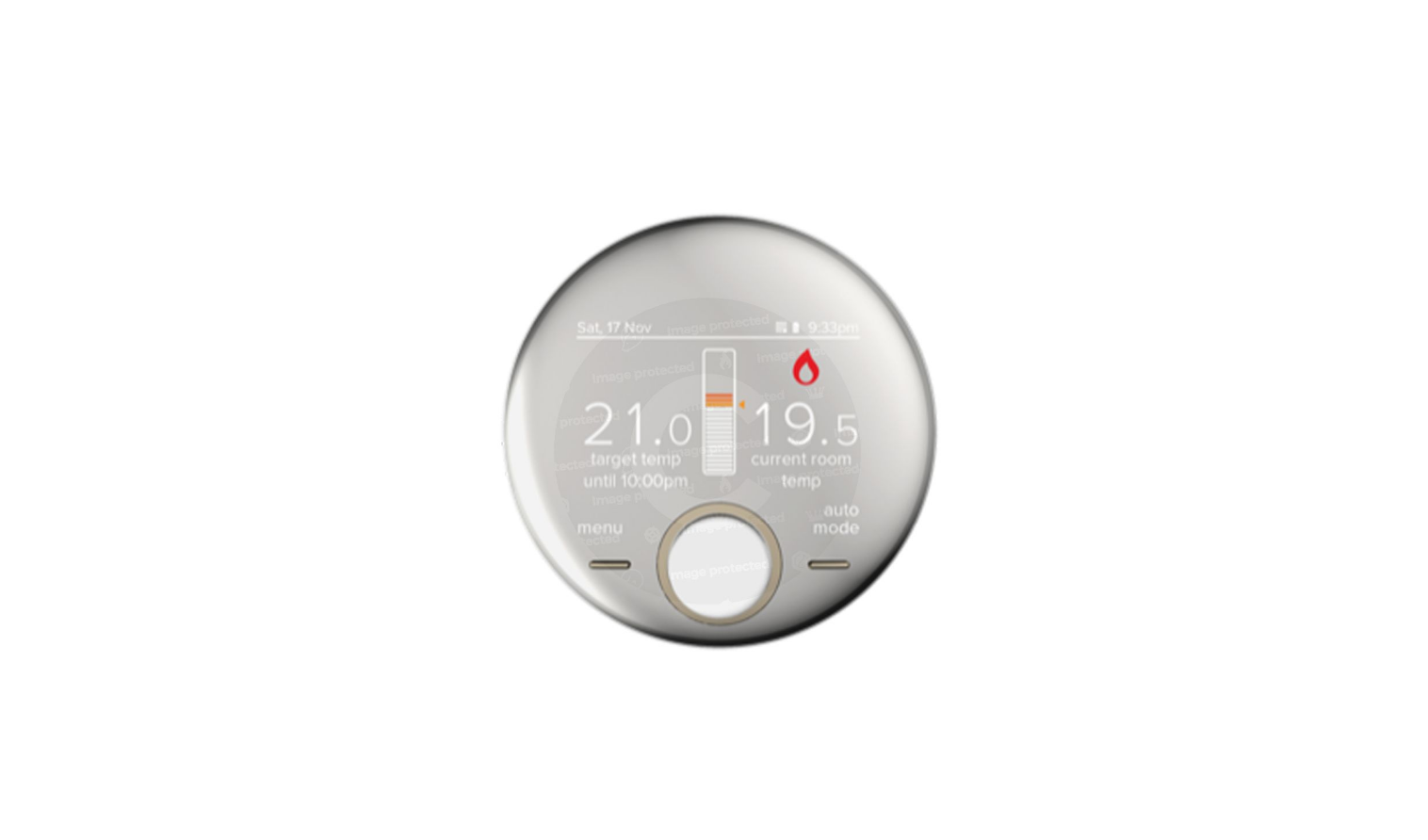
 Ideal Halo 222143 Programmable Thermostat

HALO HEAT & SYSTEM RF
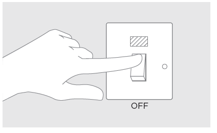
Compatible with the following boilers: Logic Heat H, Logic Heat H IE, Logic System S, Logic System S IE, Logic+ Heat H, Logic+ System S, Logic Max Heat H, Logic Max Heat H IE, Logic Max System S, Logic Max System S IE Keston System, Vogue System, Vogue GEN2 System, Vogue Max System, Vogue Max System IE. To install Halo with older boilers further details can be found at idealheating.com The Ideal Halo Heat & System RF is a wireless PRT that is paired with the Halo Smart Interface installed alongside the boiler. The Smart Interface is fitted into the Smart Interface Bracket and is wired directly to the boiler and communicates to the boiler via OpenTherm. A Smart Wiring Centre is provided to control central heating components (zone valves, cylinder thermostat, circulating pump). The Halo unit is powered by 4 AA batteries. Communication from the Smart Interface to the PRT is through Zigbee, a local RF protocol. Communication between the Smart Interface and Smart Wiring Centre is also via Zigbee removing the need to wire the Smart Wiring Centre directly to the boiler. The Halo Heat & System, including the Smart Wiring Centre and Smart Interface bracket, must be installed by a competent person with the appropriate safety qualifications. Please read the instructions carefully. Failure to follow these instructions can damage the product or cause a hazardous condition. These instructions are applicable to the Ideal boiler models stated and must not be used with any other make or model of boiler. This product must be installed to all applicable standards. Always isolate the mains supply before installing or working on any components that require a 230V ac supply.
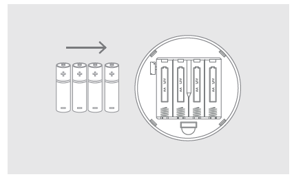
KIT CONTENTS
LOCATION GUIDELINES
The Halo Heat & System uses wireless Zigbee communication from the Smart Interface to the Smart Wiring Centre and Halo PRT up to a maximum distance of 30 meters. Occasionally house constructions and materials can reduce this communication range and it is advisable, where possible, to try and avoid directing communications through metal frames or solid concrete walls. If the distance between the Halo PRT and Smart Interface or the Smart Wiring Centre and Smart Interface is greater than 30 meters or the install location is challenging, consider using the Zigbee Booster (UIN 221132, further details available at idealheating.com)
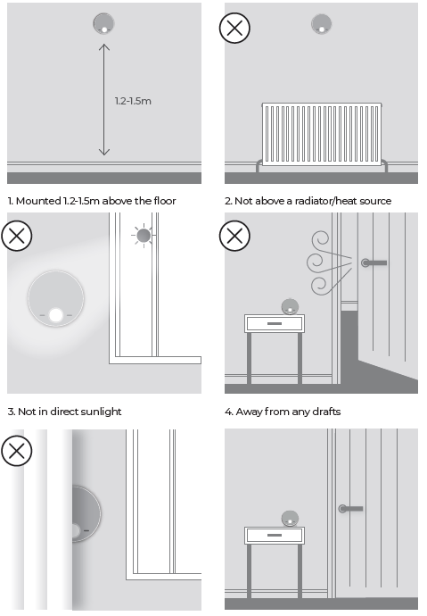
- Mounted 1.2-1.5m above the floor
- Not above a radiator/heat source
- Not in direct sunlight
- Away from any draftsNot fitted behind curtains
- Internal use only
SYSTEM OVERVIEW
This is a simplified diagram of how the Halo units, Smart Wiring Centre, and Smart Interface communicate. Some wiring and pipework have been omitted for clarity
*solid and metallic objects will reduce the maximum distance
INSTALLING THE HALO PRT
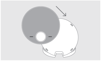
WALL MOUNTING THE HALO
If there are any concerns regarding the signal strength and location of the wall-mounted PRT it is advisable to pair the control and check the signal strength before fixing to the wall.
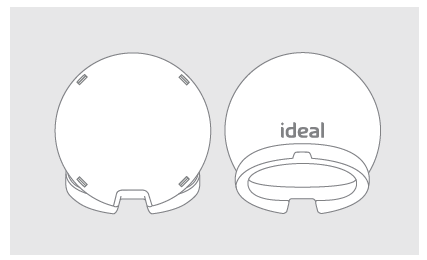
- The Halo can be installed with or without the provided trim plate.
 If no trim plate is required, use the rear housing of the Halo to position the unit on the wall, alternatively secure rear housing to trim plate. Take care not to overtighten the screws.
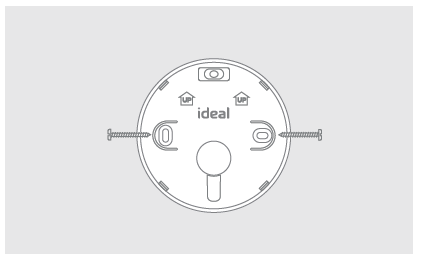
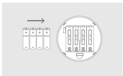
- Insert the 4 AA batteries provided into the front housing of the Halo. Pay close attention that the orientation of the batteries is as indicated in the housing
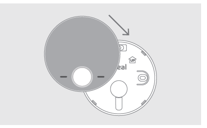
- Locate the front housing (display) in position perpendicular to the rear housing and clip into place.
DESK MOUNTING THE HALO
- The Halo has an integrated rear housing and desk stand
- Insert the 4 AA batteries provided into the front housing of the Halo. Pay close attention that the orientation of the batteries is as indicated in the housing.
- Clip the combined rear housing and desk stand into place.
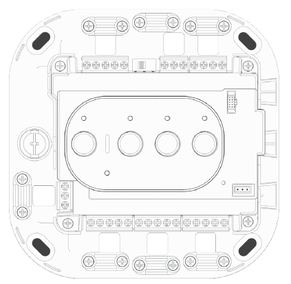
INSTALLING THE SMART WIRING CENTRE
The Smart Wiring Centre controls the operation of the zone valves for the central heating system. The Smart Wiring Centre communicates wirelessly to the Smart Interface via the Zigbee RF protocol. The Smart Wiring Centre must be mounted to a fixed surface before installation.
Removing the cover
Using a suitable screwdriver turn the locking key one-quarter and turn anticlockwise to the [UNLOCK] position. Remove the front panel by lifting the left-hand edge first. Assemble in reverse order. Always remember to lock the front panel to the Smart Wiring Centre
Wall mounting the Smart Wiring Centre
Please refer to the location guidelines before fixing the Smart Wiring Centre to the wall. Using the 4 fixing locations on the Smart Wiring Centre secure to the Wall with adequate fixings for the wall type
 Do not remove the cover unless you are qualified to do so.
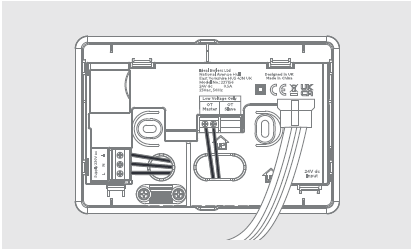
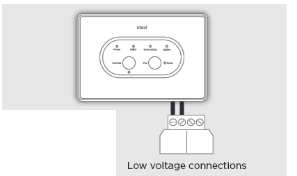
WIRING THE SMART INTERFACE
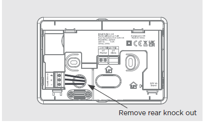
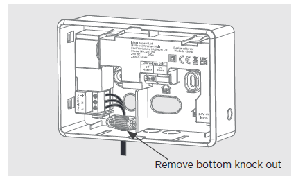
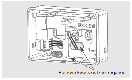
The Smart Wiring Centre must be installed by a competent person with the appropriate safety qualifications. All wiring must be adequately sheathed and insulated. Isolate any 230V ac mains supply to the Smart Wiring Centre and any other linked components before commencing work. For detailed wiring instructions please refer to the wiring diagram fold-out in the kit. This gives detailed wiring on S-plan and Y-plan systems. Ensure the selector switch is in the correct position for the installed system. Wiring can either be installed from the rear of the device through the back housing cutouts or surface mounted. When surface mounting any wiring, use the reversible omega clamps provided. Remove all appropriate cutouts on the front cover for wiring.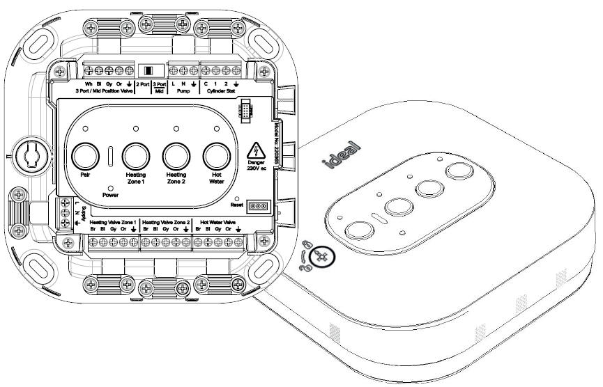
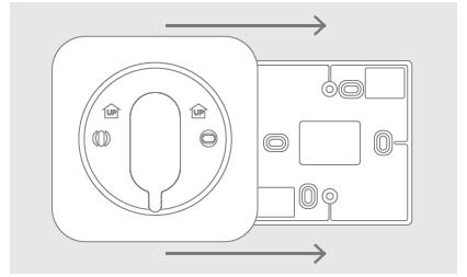
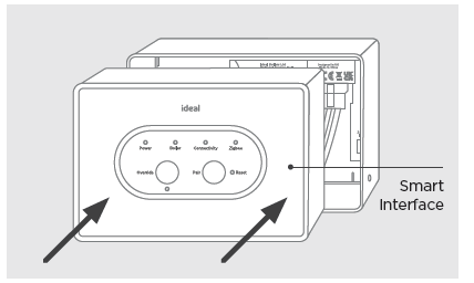
INSTALLATION OF THE SMART INTERFACE BRACKET AND THE SMART INTERFACE
To install the Smart Interface into a new boiler follow the steps below. For further details on the compatibility of older boilers please visit idealheating.com. The Smart Interface Bracket can be mounted straight to the wall or onto an existing single gang wall box
- Locate the Smart interface bracket in a suitable location close to the boiler and fuse spur as the bracket is hard wired to both.
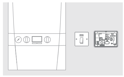
- To mount directly onto the wall, mark and drill 2 mounting holes and fix the bracket to the wall using suitable fixings for the wall type.
- To mount over the electrical box, place the bracket over the electrical box and fix it into place.
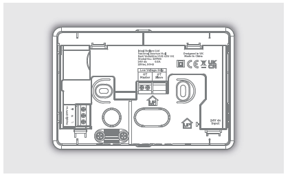
- Isolate the mains supply
- Rear cable mounting; From the fuse spur wire the Live, Neutral and Earth connections into the left hand side connections in the Smart Interface Bracket marked L, N, (E).
- Surface cable mounting; From the fuse spur wire the Live, Neutral and Earth into the left hand side connections in the Smart Interface Bracket marked L, N, (E). Using the cable clamp provided.
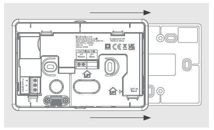
- Rear or surface mount options are available. Install the Smart Interface by connecting the plug on the Smart Interface to the connector in the bracket.
- Surface cable mounting; From the fuse spur wire the Live, Neutral and Earth into the left-hand side connections in the Smart Interface Bracket marked
- Carefully push the Smart Interface into the bracket
- Locate the wiring terminal within the boiler control box (230V connections are on the left and low voltage on the right).Locate the wiring terminal within the boiler control box (230V connections are on the left and low voltage on the right).
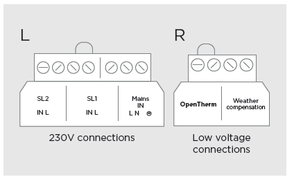
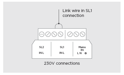
- If an existing 230V signal is already installed remove any existing wiring from the 230V connections and add the link wire to the SL1 connections
- Take the cable that is wired into the bracket OpenTherm Master terminals and connect into the OpenTherm connections in the boiler ensuring it is run through the strain relief (in new boilers remove the link positioned here before wiring).
Do not connect to the 230V ac connections
PAIRING OF THE SMART INTERFACE TO THE SMART WIRING CENTRE
- Turn the power back on to the boiler and Smart Wiring Centre

- The Smart Wiring Centre will power up and automatically enter into pairing mode shown by the pairing LED flashing red, this mode will be active for 10 minutes. If further time is required after 10 minutes hold the pair button until the pair light flashes red.
- The Halo Smart Interface will power up and begin setup, this can take up to 90 seconds. Once setup is complete the green Power LED should be the only LED illuminated.
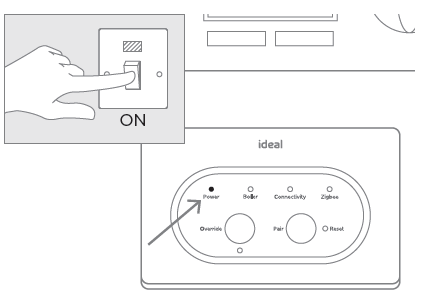
- Check the Smart Interface connection to the boiler by pressing the override button. The override LED should be green and the boiler will fire. Press the override button again to switch off the boiler, the override LED should now go out
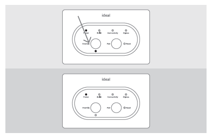
- Press and hold the Pair button on the Smart interface until the Zigbee LED flashes red.
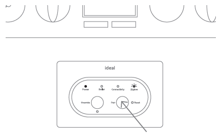
- Pairing will now commence between the units. To show a successful pairing process the Pair LED on the Smart Wiring Centre will turn Solid Green.
PAIRING OF THE HALO
- When the batteries are inserted, the Halo PRT will power up automatically.
- The device will prompt pairing with the Smart Interface using an easy step-by-step process.
- Simply follow the on-screen guide to select the type of boiler, Heat & System, and the system type, heating and hot water.
- The Halo PRT screen will show “Pairing in Progress”, then “Synchronisation in Progress” and then “Pairing Complete” when the Halo PRT has successfully connected to the Smart Interface.
- The device will automatically prompt set up of the time and date.
- There is the opportunity to add an installer contact phone number into the device at this stage, if not changed this will default to the Ideal Heating Customer Service number.
- The home screen will be displayed showing the current and target temperature and the temperature bar. The Zigbee communication icon will also be visible on the display.
- Once the Halo PRT is paired to the Smart Interface press and hold the pair button on the Smart Interface until the Zigbee LED goes to solid green.
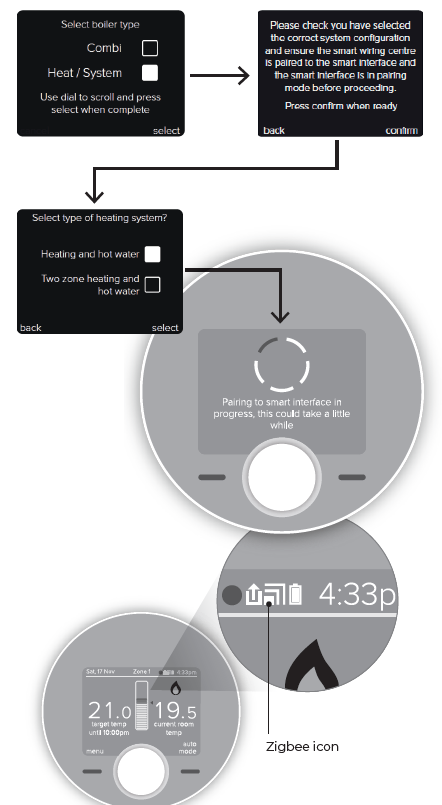
For multizone systems please see the installation guide in the Halo Heat & System 2-Zone Upgrade kit for step 3 selections.
CONNECTING THE HALO TO THE INTERNET*
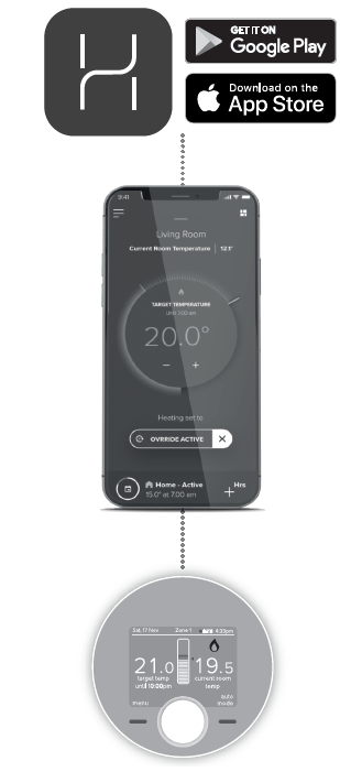
- Check the home router is connected to the internet.
- Ensure 2.4GHz is enabled on the home Wi-Fi router.
- If it has not been done already, download and install the Ideal Halo app onto the householder’s phone. (Available on Google Play or the Apple App Store.)
- Open the Ideal Halo app, tap on create an account and follow the in-app instructions.
- Once an account has been set up the app will automatically guide the user through connection of Halo. This will involve using the app to link the Halo Smart Interface to the home Wi-Fi network by following the instructions on the screen.
- The householder will need the name of their home Wi-Fi network and the password or network key to complete the setup.
ADVANCED SETTINGS
| Description | Factory setting | New setting |
| Optimized startThe boiler starts heating in advance of schedule so heating reaches the required temperature at the time specified. | OFF | |
| Optimized stopBoiler stops heating in advance of schedule so heating reaches the required temperature at the time specified. | OFF | |
| Delayed startIf the room temperature is close to target temperature the heating start time is delayed to save energy. | OFF | |
| Display toleranceSelect the display tolerance of the room temperature, this can be set at increments of 0.5 or 0.1°C. | 0.1°C | |
| Temperature offsetting tune the room temperature display -2.5 to 2.5°C. | 0°C | |
| Daylight saving time automatically move to daylight saving. | ON | |
| Frost protectionThe temperature that will be used to protect your home when the thermostat is off. Can be set 5°C. | 50C | |
| Service phone number opportunity to input Installer contact number for service reminders. | Ideal Heating number |
HALO FEATURES AND CONFIGURATION
| Menu options | Action |
| Holiday | Holiday mode allows the device to be switched off for a predefined period of time then automatically returns to the pre-programmed heating schedule. |
| Timed heating schedule | Set a heating schedule with up to 6 periods per day. |
| Timed hot water schedule | Set a hot water schedule with up to 6 periods per day. |
| Support | Includes information such as software version and key contact numbers. |
| Fault page | Shows the latest fault code and fault description. |
| Time and date | Time and date are set on power up and can be adjusted via the menu. |
| Advanced settings | Advanced features of the device setup should be set by a competent person. |
| Landlord settings | Specific settings for landlords. |
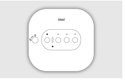
SMART INTERFACE LED TO KEY
| LED | Status |
| Power | Green – Power ONNo illumination – No power |
| Boiler | Green – DemandNo illumination – No demand |
|
Connectivity |
Not used |
|
Zigbee |
No illumination – No Zigbee network Green – Zigbee network active Green flashing – Identify function Red flashing – PairingRed flashing then orange – Zigbee network deletion
Orange for 30s – Factory reset |
| Override | Green – Override active*Green flashing – Failsafe active* No illumination – Override OFF* |
*Override and Failsafe only active when communication is lost between the Halo PRT and Smart Interface. See Halo User Guide for more information.SMART WIRING CENTRE LED KEY
| LED | Status |
| Power | Green – Power ONRed Flashing – Override
No illumination – No power |
|
Pair |
No illumination – No Zigbee network Green – Zigbee network active Green flashing – Identify function Red flashing – PairingOrange then flashing red – Smart Wiring Centre deleted from Zigbee network |
| Heating Zone 1 | Green – DemandNo illumination – No demand |
| Heating Zone 2 | Not used |
| Hot Water | Green – DemandNo illumination – No Demand |
Override and Failsafe only active when communication is lost between the Smart Wiring Centre and Smart Interface. This allows for manual opening and closing of the zone valves.
COMMISSIONING CHECKLIST
| Use the “Identify” function to confirm successful pairing has taken place. A short press on the Pair button on the Smart Interface. Press Pair button again to exit “Identify” function. | Zigbee LED on Smart Interface flashes green | |
| Halo home screen flashes to indicate successful pairing | ||
| Zigbee LED on Smart Wiring Centre flashes green | ||
| Halo is positioned in the homeowners chosen location if desk mounted. | ||
| Check RSSI (Received Signal Strength Indication) of the Zigbee wireless connection via support page on the PRT (access via the menu). | Target RSSI between 0 and -65 and text green | |
| On the Halo set the mode to AUTO then increase the temperature to 30°CNote: Boiler will (turn on) once zone valve is in fully open position | Flame icon ON | |
| Heating zone on Smart Wiring Centre OFF | ||
| Boiler ON | ||
| Boiler LED on Smart Interface ON (Green) | ||
|
On the Halo set the heating mode to AUTO then decrease the temperature to 5°. |
Flame OFF | |
| Heating zone on Smart Wiring Centre OFF | ||
| Boiler OFF | ||
| Boiler LED on Smart Interface OFF | ||
| On the Halo set the hot water mode to ON.
Note: Boiler will (turn on) once zone valve is in fully open position |
Hot water ON (icon turns orange) | |
| Hot water zone on Smart Wiring Centre ON | ||
| Boiler ON | ||
| Boiler LED on Smart Interface ON (Green) | ||
|
On the Halo set the hot water mode to OFF. |
Hot water OFF (icon turns white) | |
| Hot water zone on Smart Wiring Centre OFF | ||
| Boiler OFF | ||
| Boiler LED on Smart Interface OFF | ||
|
Description |
Confirmed | ||
| Zone 1 | Hot Water | ||
| Check the Smart Interface indication is correct. | Power LED green Zigbee LED green Connectivity LED green | ||
| Check the Smart Wiring Centre indication is correct. | Power LED green Pair LED green | ||
| Full battery level indication on Halo home screen. | |||
| Zigbee network icon is present on the Halo home screen. | |||
| Cloud network icon is present on Halo home screen.*Halo Combi Wi-Fi only | |||
| Time and date correct. | |||
| Zone valves labelled using provided labels. | |||
| Installer contact details inputted if required. | |||
| Suitable schedule has been entered for the user.*remember to set both heating and hot water back to users desired mode | |||
| General overview of operation provided to user – refer to user guide. | |||
| Any advanced settings changes have been recorded. | |||
| Remember to leave this guide with the householder. | |||
TROUBLESHOOTING
| No power LED on Smart Interface | Check Smart Interface is wired to the fuse spur. Check fuse spur is on. |
| Halo screen is flashing continuously | The Smart Interface is in ‘Identify’ mode press the Pair button to cancel this mode. |
| Boiler fails to fire when increasing target temperature on the Halo | Check the target temperature is above current temperature. Check Smart Interface power LED is green.Check Smart Interface is wired securely to the boiler. |
|
Halo screen shows failed to pair |
Check Smart Interface is in paring mode (Zigbee LED flashing red). Check distance between Smart Interface and Halo (see section B).
Reset Smart Interface by inserting a paperclip or pen tip into reset button. Start pairing mode again on the Smart Interface and press retry on the Halo. If the situation persists then consider using Zigbee Booster (available separately) or mounting the Smart Interface closer to the PRT. |
| Halo screen shows Replace Halo | If you have no other Halo thermostats connected to the Smart Interface or are not replacing an existing Halo then press accept. |
| In the support page the Zigbee RSSI is lower than -65 | Consider moving the Halo closer to the Smart Interface.If the situation persists then consider using Zigbee Booster (available separately) or mounting the Smart Interface closer to the PRT. |
| Deleting Halo from the Zigbee Network | On the Halo press the dial and the right hand key together for 15 seconds, this will delete the Halo from the Zigbee network and factory reset the device. |
| Deleting Smart Wiring Centre from the Zigbee Network | On the Smart Wiring Centre press and hold pair button, the Pair LED on the Smart Wiring Centre will flash red then orange to confirm the device has been deleted from the network. |
| Deleting Zigbee Network | To delete all devices from the Zigbee network, press and hold the Pair button on the Smart Interface. The Zigbee LED on the Smart Interface will flash red and then orange to confirm the devices have been deleted from the network. |
| Factory reset of the Smart Interface | Press and hold the Pair button and the Override button for 20 seconds.The Smart Interface will delete all Zigbee devices from the network, this will take approximately 20 seconds and detach from the Wi-Fi network if the control is a connected control.
On disconnection, the Smart Interface will automatically begin the setup process as per section H.2b. of the installation guide. |
Hereby, Ideal Boilers Ltd declares that this device (model 222143) is in compliance with: Directive 2014/53/EU.
The full text of the EU declaration of conformity is available at the following internet address idealheating.com
UIN: 227167 A01RF frequency: 2405 –2480MHz Max. RF output power: 10dBm
- Ideal Boilers Ltd
- National Avenue
- Hull, HU5 4JN
- T: 01482 498660
- E: [email protected]
Reference
Download MANUALS
Ideal Halo 222143 Programmable Thermostat Installation Guide
![]()
Ideal Halo 222143 Programmable Thermostat Installation Guide
Leave a Reply