American Standard ACONT402AN32DA Electronic Non-Programmable Thermostat
 Introduction
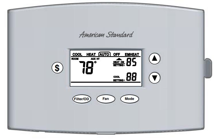
ACONT402AN32DA is a digital non-programmable 3Heat/ 2 Cool/Heat Pump/ Heat-Cool wall mounted low voltage (24VAC) Comfort Control with backlit LCD and keypad. It maintains room temperature by controlling the operation of heating, cooling, heat pump and dual fuel systems. The Comfort Control is easily configured for heat pump or cooling only and gas or electric or dual fuel heat applications via the user friendly Installer Setup menu. The Comfort Control features include separate heating and cooling setpoints, selectable auto or manual changeover, adjustable energy saving mode, adjustable filter reminder, outdoor temperature sensing, remote room sensing and remote humidistat input. Setup selections and diagnostics are stored indefinitely in the Comfort Controls nonvolatile memory eliminating the need for battery backup.
Safety Considerations
Read the following manufacturer instructions carefully. Follow all local codes during installation. All wiring must conform to local and national electrical codes. Improper wiring or installation may damage the comfort control.
Recognize safety information. This is the safety alert symbol
When you see this symbol on the equipment and in the instruction manual, be alert to the potential for personal injury.
Understand the signal words DANGER, WARNING and CAUTION. These words are used with the safety-alert symbol. DANGER identifies the most serious hazards which will result in severe personal injury or death. WARNING signifies a hazard which could result in personal injury or death. CAUTION is used to identify unsafe practices which could result in minor personal injury or product and property damage.
Note: Read the entire instruction manual before starting the
installation.
Application Hook-Up Diagrams
Dual Fuel* FIG
- 1-2 Stage/Step Heat Pump 2 Stage VS Gas Furnace w/ BK DF-1
- 2 Stage Heat Pump 2 Stage VS Gas Furnace no BK DF-2
- 2 Step Heat Pump 2 Stage VS Gas Furnace no BK DF-3
- 1 Stage Heat Pump 2 Stage VS Gas Furnace no BK DF-4
- 1 Stage Heat Pump 1-2 Stage Gas Furnace no BK DF-5
Heat Pump
- 1-2 Stage/Step Heat Pump VS Air Handler w/ BK HP-1
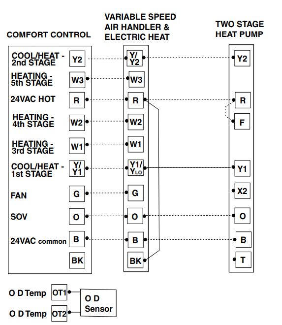
- 2 Stage Heat Pump VS Air Handler no BK HP-4
- 2 Step Heat Pump VS Air Handler no BK HP-5
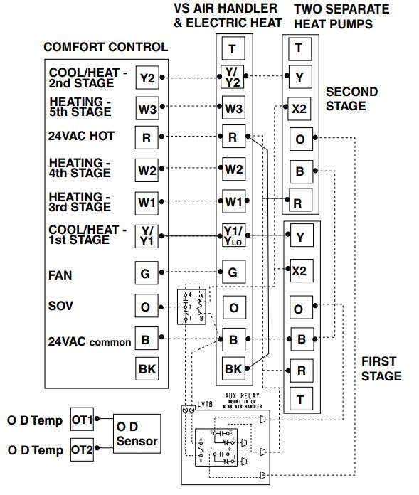
- 2 Heat Pumps Split Coil VS Air Handler w/ BK HP-2
- 2 Heat Pumps Split Coil VS Air Handler no BK HP-3
- 1 Stage Heat Pump VS Air Handler no BK HP-6
- 1 Stage Heat Pump Air Handler no BK HP-7
Cooling
- 1-2 Stage/Step Cooling VS Indoor w/ BK CL-1
- 2 Stage Cooling VS Indoor no BK CL-3
- 2 Step Cooling VS Indoor no BK CL-4
- 2 Cool Units Split Coil VS Air Handler w/ BK CL-2
- 2 Cool Units Split Coil VS Air Handler no BK CL-5
- 1 Stage Cooling VS Indoor no BK CL-6
- 1 Stage Cooling non-VS Indoor no BK CL-7
- 1 Stage Cooling 1 Stage Oil Furnace no BK OIL-1
- * Requires external relay for Oil furnace applications. TAYPLUS103 not required
BAYSENS01ATEMPA for outdoor temperature sensing and display and optional control is included.
Optional Humidistat: ASYSTAT625A
Optional Remote Indoor Sensor: ZZSENSAL0400AA
Installer’s Guide
Product Specifications
- Power Source: 20-30VAC, Class II, 50/60Hz.
- System Mode: Heat, Cool, Auto, Emergency Heat and Off
- Fan Mode: Auto and On
- Cooling setpoint temperature range: 65F – 90F, 18.0C – 33.0C, 1F and 0.5C resolution.
- Heating setpoint temperature range: 40F- 85F, 5.0C – 30.0C, 1F and 0.5C resolution.
- Default set points: 68F, 20.0C Heat, 78F, 25.5C Cool
- Storage Range: -40F to 140F, 5% – 90% RH non-condensing.
- Operating Temperature Range: 32F – 110F, 5 – 90% RH non-condensing.
- Outdoor Temperature Display Range: -40F – 140F.
- Minimum Cycle Off Time Delay: Cooling – 5 minutes, Heating – 1 minute.
- Use minimum 18 gauge NEC-approved control wiring.
CAUTION
To prevent shortening its service life, the control should not be installed until construction is completed.
Installation
Comfort Control – Location
The Comfort Control should be mounted approximately 60” (1.5m) off the floor on an interior partition wall. Never install the Comfort Control on an outside wall. For proper temperature sensing, avoid mounting the Comfort Control where it will be exposed to heat radiated from lamps, sun light, fireplaces or any other radiant heat sources.
Avoid locations close to windows, behind doors or alcoves with poor air circulation, adjoining outside walls, or doors that lead to the outside.
Select a location that prevents the Comfort Control from being directly exposed to air currents from supply registers. Mount the Comfort Control on a section of interior wall that does not contain hot and cold water pipes or ductwork.
Outdoor Sensor – BAYSEN01ATEMPA – Location
Careful consideration of the following recommendations will help the outdoor sensor provide continuous accurate readings:
- Mount the outdoor sensor on the north-facing side of the building in an area where it is exposed to freely circulating airflow and out of direct sunlight.
- Do not allow hot air airflow from the attic or drafts from inside exterior walls to bias the sensor’s operation. Always seal the hole where control wiring passes to the outside of the structure. Use non-hardening caulk, putty, or insulation.
- Avoid locations such as near dryer vents or placing the sensor close to, or directly above the outdoor unit where it would be exposed to hot discharge air from the condenser fan.
- The maximum length of field wiring cable to sensor is 200 feet.
- The minimum wire gauge is 18AWG.
Mounting and Wiring
- Turn OFF all power to heating and cooling equipment.
- If an existing thermostat is being replaced:
- Remove the existing thermostat from the wall.
- Disconnect wires from the existing control, one at a time.
- As each wire is disconnected, record wire color and terminal marking.
- Discard or recycle old thermostats.
Mercury is a hazardous waste and MUST be managed properly. If Comfort Control is replacing a thermostat that contains mercury in a sealed tube, do not place your old thermostat in the trash. Contact your local waste management authority for instructions regarding recycling and the proper disposal of an old thermostat.
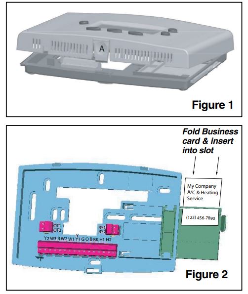
- Separate the control from the mounting base to expose mounting holes by pressing the release button A on the bottom of the control with the thumb of one hand while gripping the subbase by the mounting holes with the other hand. Lift out and up. See Figure 1.
- Slide the mounting base drawer out to expose all the mounting holes. Route control wires through the large hole in the mounting base.
Level mounting base against wall (for aesthetic value only) and mark the wall through 2 mounting holes. See Figure 2. - Drill two mounting holes in wall where marked.
- Secure mounting base to wall with 2 screws (use anchors provided if needed). Additional mounting holes are available for more secure mounting if needed. Make sure all wires (including the 2 outdoor sensor wires) extend through hole in the mounting base.
- Adjust length and routing of each wire to reach the proper terminal on the connector block on the mounting base. Strip only 1/4-in. of insulation from each wire to prevent adjacent wires from shorting together when connected.
- Match and connect control wires to proper terminals on the connector block. (See the following wire diagrams).
- Push any excess wire back into the wall and seal the hole to prevent air leaks.
Note: Air leaks in the wall behind the control can cause improper operation. - Check the operation of the business card drawer. Verify that it slides in and out without binding.
- Reinstall the control on its mounting base by aligning the control at the top of the mounting base. Swing the control downward and gently press the bottom of the control into position until latch button A engages. See Figure 1.
- Turn ON the power to the heating and cooling equipment.
SETUP
Enter INSTALLER Setup:
(See Table 3, steps 1 – 49 for option details)
- Set System Mode to OFF
- Set Fan to AUTO
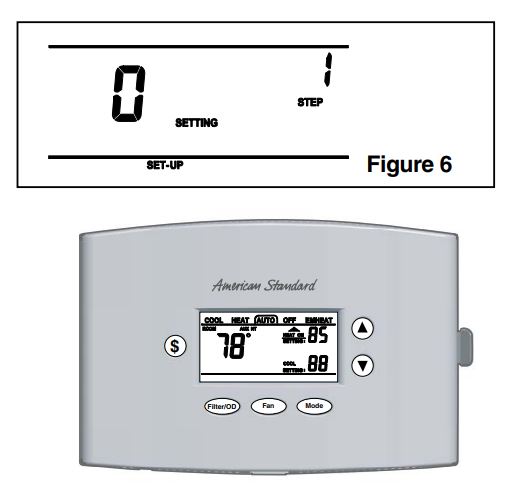
- Press and hold Mode and Up Arrow at the same time.
- SET-UP will appear on display. See Figure 6.
- Enter USER Setup:
(See Table 3A, steps 50-62 for option details) Press and hold Mode and Fan at the same time.
Note: Allow a minimum of 5 seconds after saving selections (Step 99 – SA) for the control to write selections to memory. If power is lost or removed prior to the 5-second elapsed time, the selections may be lost and must be re-entered. If the SERVICE icon is flashing on the control LCD, press any key and check/re-enter setup choices.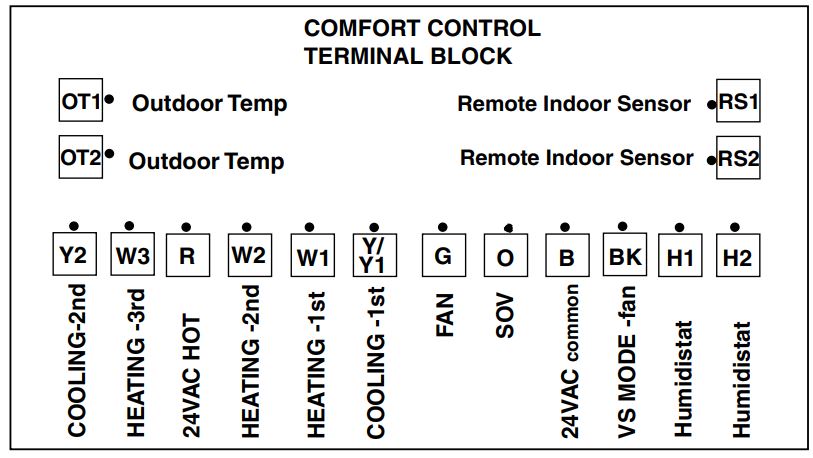
Keypad Navigation:
Use the Mode and Fan buttons to navigate forward and backward through the configuration and Manual Test Mode steps.
Press Mode to advance forward to the next step.
Note: Dual Fuel Applications. When the system type is HP and the Indoor Heater Type is Gas or Oil (Dual Fuel System) the JP1 jumper on the PCB must be cut.
Press Fan to return to the previous step.
Use the Up and Down arrow buttons to select or change setup options.
Lock – Unlocok Keypad:
Press and hold Up Arrow and Down Arrow at the same time.
(“Keypad Locked” will display on LCD screen)
Defeat Equipment Time Delay:
(Current Cycle only) Press Mode and Down Arrow at the same time.
Checkout
There are two methods of verifying that the Comfort Control operates the system as intended.
Method 1: Normal Mode
This can be accomplished by pressing the appropriate keypad button(s) to cycle the system through each of the available modes and increasing or decreasing the setpoint to activate and deactivate the cycle. The minimum on and off cycle time delays, selected during the setup, will be enforced. Press the appropriate keypad button for the filter timer, outdoor temperature display and energy savings features to verify they are set to the end user’s desired preference.
Method 2: Manual Test Mode
The Comfort Control’s load outputs can be verified using the manual test mode. See Table 1 for navigating through the manual test mode steps.
To Enter The Manual Test Mode:
- Set System Mode to OFF
- Set Fan to AUTO
- Press and hold Mode and Down Arrow at the same time.
The Manual test mode will time out and return to normal operation after 4 minutes from the last key press.
NOTE: The manual test mode allows the installer to energize the G fan relay, Table 1, Step 70, and then advance to Step 72 to energize the Y compressor output with the fan still operating. It is recommended that this method be used to prevent damage to the compressor.
| Table | 1 | Manual Test Mode | |||
| Menu Item
(Press Mode or Fan) |
Default |
Setting (Choices) (Press Up or Down
Arrow) |
Step
(Press Mode or Fan) |
||
| G – Fan Relay | Off | On / Off “6” | 70 | ||
| BK – BK Output | 35% | 35% – 100% | 71 | ||
| Y1 – Compressor
(G – must be ON) |
Off |
On / Off “y” |
72 |
||
| Y2 – Compressor Contactor
(G – must be ON) |
Off |
On / Off “y2” | 73 | ||
| O – Switch Over Valve | Ht | CL / Ht “O” | 74 | ||
| W1 – Heating Relay | Off | On / Off ‘U1″ | 75 | ||
| W2 – Heating Relay | Off | On / Off ‘U2″ | 76 | ||
| W3 – Heating Relay | Off | On / Off “U3” | 77 | ||
|
LCD |
“SC” |
— |
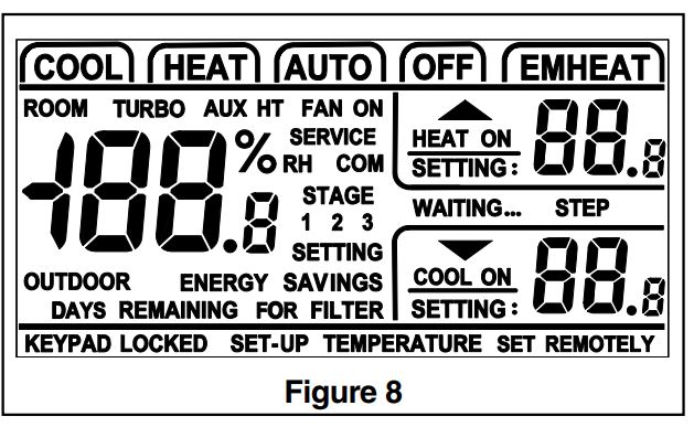
All Icons On (see fig 8) All Icons Off |
78 |
|
| Factory Use Only | Press and hold MODE to advance to step 80 and press “$” to exit | 79-89 | |||
| Table 2 | |||||
|
T deg F |
RESISTANCE (OHMS X 1000) 10K THERMISTOR |
T deg F |
RESISTANCE (OHMS X 1000) 10K THERMISTOR |
T deg F |
RESISTANCE (OHMS X 1000) 10K THERMISTOR |
| -15 | 138.9 | 35 | 30.0 | 80 | 9.3 |
| -10 | 117.7 | 40 | 26.1 | 85 | 8.3 |
| -5 | 99.9 | 45 | 22.7 | 90 | 7.3 |
| 0 | 85.1 | 50 | 19.9 | 95 | 6.5 |
| 5 | 72.7 | 55 | 17.4 | 100 | 5.8 |
| 10 | 62.3 | 60 | 15.3 | 105 | 5.2 |
| 15 | 53.5 | 65 | 13.5 | 110 | 4.7 |
| 20 | 46.1 | 70 | 11.9 | 115 | 4.2 |
| 25 | 39.8 | 75 | 10.5 | 120 | 3.8 |
| 30 | 34.5 | ||||
WIRING DIAGRAM
- DUAL FUEL ONE OR TWO-STAGE OR TWO-STEP HEAT PUMP TWO-STAGE VS GAS FURNACE BK ENABLED
Note B – Cut/remove the factory-installed “BK” jumper at the indoor unit.
Note C – For Dual Fuel, cut the JP1 jumper on the Comfort Control.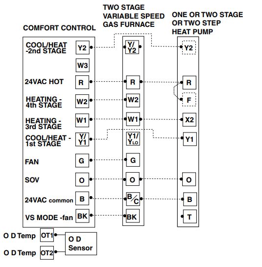
- DUAL FUEL TWO-STAGE HEAT PUMP TWO STAGE VS GAS FURNACE BK DISABLED
Note C – For Dual Fuel, cut the JP1 jumper on the Comfort Control.
NOTE: See Fig. OIL-1 for external relay connections for oil furnaces.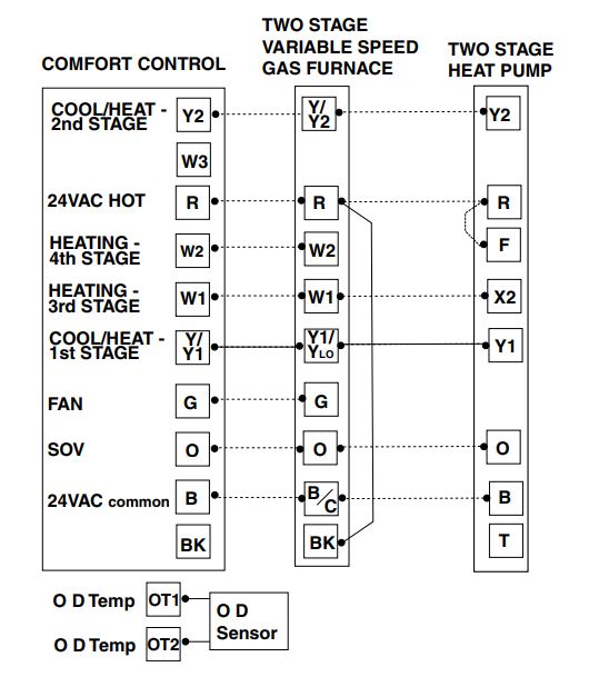
- DUAL FUEL TWO-STEP HEAT PUMP TWO-STAGE VS GAS FURNACE USE ONLY WITH 16 SEER CONDENSER BK DISABLED
Note A – The installer must jump “R” to “O” at the LVTB.
Note B – Cut/remove the factory-installed “BK” jumper at the indoor unit.
Note C – Cut the JP1 jumper on the Comfort Control, for Dual Fuel.
NOTE: See Fig. OIL-1 for external relay connections for oil furnaces.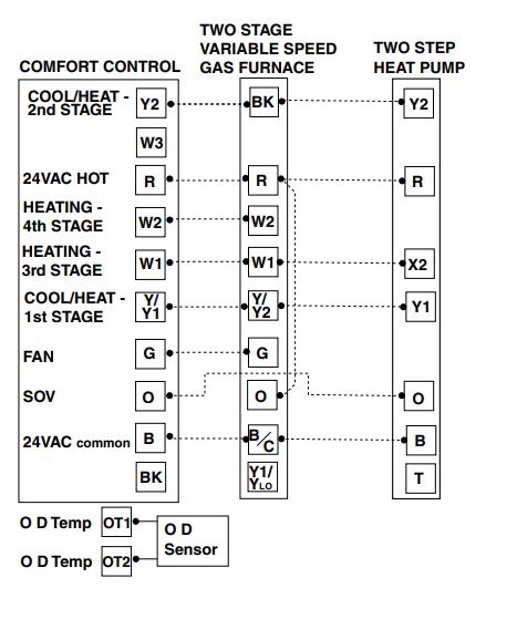
- DUAL FUEL SINGLE-STAGE HEAT PUMP TWO STAGE VS GAS FURNACE BK DISABLED
Note C – For Dual Fuel, cut the JP1 jumper on the Comfort Control.
NOTE: See Fig. OIL-1 for external relay connections for oil furnaces.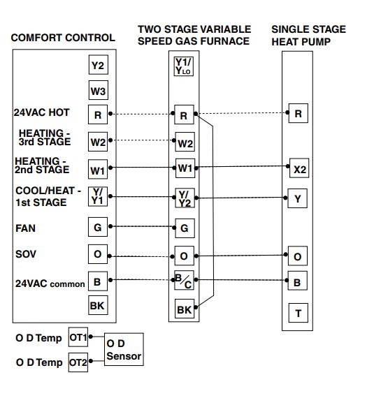
- DUAL FUEL SINGLE-STAGE HEAT PUMP NON-VARIABLE SPEED GAS FURNACE BK DISABLED
Note C – For Dual Fuel, cut the JP1 jumper on the Comfort Control.
NOTE: See Fig. OIL-1 for external relay connections for oil furnaces.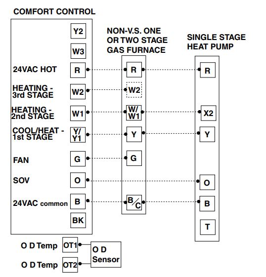

- ONE OR TWO-STAGE OR TWO-STEP HEAT PUMP VARIABLE SPEED AIR HANDLER BK ENABLED
Note B – Cut/remove the factory-installed “BK” jumper at the indoor unit.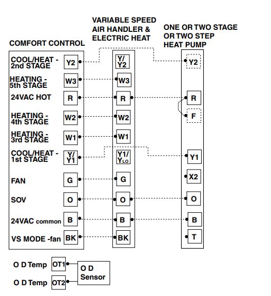
- TWO HEAT PUMPS SPLIT COIL VARIABLE SPEED AIR HANDLER BY ENABLED
Note B – Cut/remove the factory-installed “BK” jumper at the indoor unit.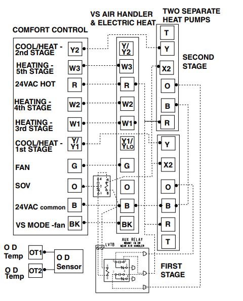
- TWO HEAT PUMPS SPLIT COIL VARIABLE SPEED AIR HANDLER BY DISABLED
- TWO-STAGE HEAT PUMP VARIABLE SPEED AIR HANDLER BK DISABLED
- TWO-STEP HEAT PUMP VARIABLE SPEED AIR HANDLER BK DISABLED
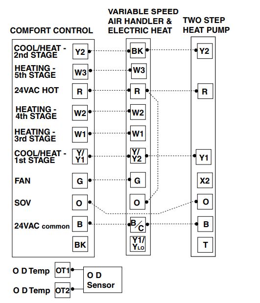
Note A – The installer must jump “R” to “O” at the LVTB.
Note B – Cut/remove the factory-installed “BK” jumper at the indoor unit. - SINGLE-STAGE HEAT PUMP VARIABLE SPEED AIR HANDLER BK DISABLED
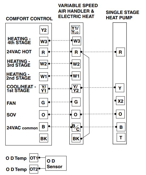
- SINGLE-STAGE HEAT PUMP NON-VARIABLE SPEED AIR HANDLER BK DISABLED
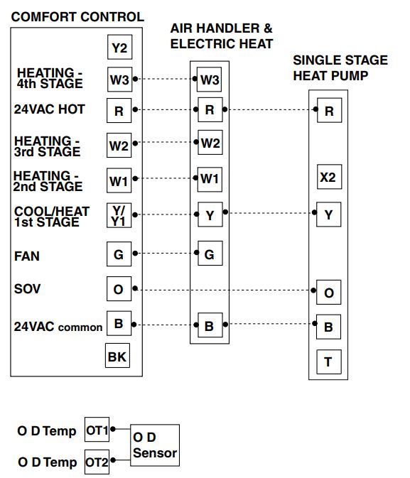
- ONE OR TWO-STAGE OR TWO-STEP COOLING VARIABLE SPEED INDOOR BK ENABLED
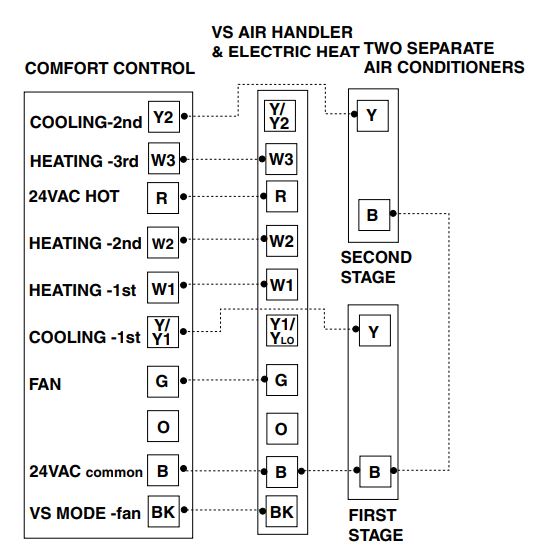
Note B – Cut/remove the factory-installed “BK” jumper at the indoor unit.
NOTE: See Fig. OIL-1 for external relay connections for oil furnaces.
NOTE: Two additional wires are required for Outdoor Temperature Sensor. - TWO STAGE COOLING SPLIT COIL VARIABLE SPEED AIR HANDLER BK ENABLED
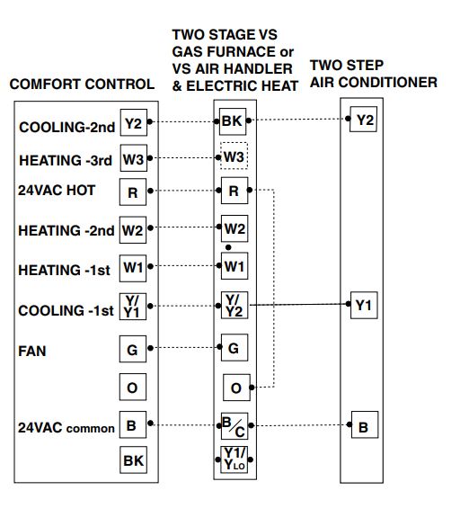
Note B – Cut/remove the factory-installed “BK” jumper at the indoor unit.
NOTE: Two additional wires are required for Outdoor Temperature Sensor. - TWO-STAGE COOLING VARIABLE SPEED INDOOR BK DISABLED
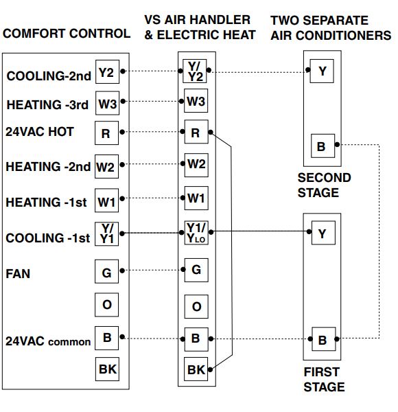
NOTE: See Fig. OIL-1 for external relay connections for oil furnaces.
NOTE: Two additional wires are required for Outdoor Temperature Sensor. - TWO STEP COOLING VARIABLE SPEED INDOOR BK DISABLED
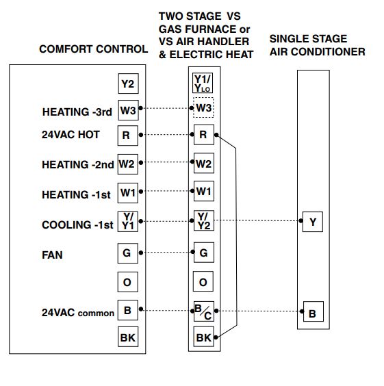
Note A – The installer must jump “R” to “O” at the LVTB.
Note B – Cut/remove the factory-installed “BK” jumper at the indoor unit.
NOTE: See Fig. OIL-1 for external relay connections for oil furnaces.
NOTE: Two additional wires are required for Outdoor Temperature Sensor. - TWO STAGE COOLING SPLIT COIL VARIABLE SPEED AIR HANDLER BK DISABLED
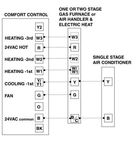
NOTE: Two additional wires are required for Outdoor Temperature Sensor. - SINGLE-STAGE COOLING VARIABLE SPEED INDOOR BK DISABLED

NOTE: See Fig. OIL-1 for external relay connections for oil furnaces.
NOTE: Two additional wires are required for Outdoor Temperature Sensor.
| Table 3 INSTALLER SETUP (ISU)
*see notes at the bottom of setup (ISU) Table 3A |
2nd Stage Compressor
Heating Cycles Per Hour |
3 |
2 – 6 CPH |
26 |
| 1. Set System MODE to OFF
2. Set FAN to AUTO 3. Press and hold MODE and Up arrow at the same time.
Step Menu Item Factory Setting (Choices) (Press Setting (Press UP or DOWN arrow) Mode Fan) Error Count 0 None 1 Software Version None 2 Configuration None 3 Signature – LoByte Configuration 4 Signature – HiByte None System Type 1 1=AC,2=HP 5 0=None 6 Compressor Stages 2 1=Single Stage 2=Two Stage/Two Step Compressor Type 0 0=Two Step, 1=Two Stage 7 1=Gas,Oil 8 Indoor Heater Type 1 2=Electric 3=Wet Heat
0=None Indoor Heater Stages 2 1=Single Stage Heater 9 2=Two Stage Heater 3=Three Stage Heater
0=None Outdoor Sensor 0 1=Has Sensor for Display Only 10 2=Has Sensor for Display and for Control
BK Output 1 0 = BK Disabled 11 1 = BK Enabled
1 = No Delay 2 = 1 Minute @ 50%, 7.5 Minutes @ 80% Variable Speed Blower 3 = 1 Minute @ 50%, 4 Minutes @ 80% 12 Turn-On Delay Profile 1 4 = 7.5 Minutes @ 80% 5 = 4 Minutes @ 80% 6 = 1 Minute @ 50% 7 = 30 Second Delay
1 = No Delay 2 = 1.5 Minutes @ 100% Variable Speed Blower 3 = 45 Seconds @ 100% 13 Turn-Off Delay Profile 1 4 = 30 Seconds @ 50% 5 = 1.5 Minutes @ 50% 6 = 3 Minutes @ 50% 7 = 30 Seconds @ 35%
Compressor 65% Two Step Range: 55%-80% 14 Low Stage Airflow 50% Two Stage Range: 35%-60%
Heat Pump Warm Air Discharge 0 0=Disabled,1=Enabled 15
Non-Variable Speed 0 0 – 30 Seconds 16 Cooling Blower ON delay
Non-Variable Speed 0 0 – 90 Seconds 17 Cooling Blower OFF delay
Non-Variable Speed Compressor 0 0 – 30 Seconds 18 Heating Blower ON delay
Non-Variable Speed Compressor 0 0 – 90 Seconds 19 Heating Blower OFF delay
1st Stage Compressor 3 2 – 6 CPH 20 Cooling Cycles Per Hour
1st Stage Compressor Cooling 3 1 – 15 Minutes 21 Minimum On Time
2nd Stage Compressor 22 Cooling Cycles Per Hour 3 2 – 6 CPH 2nd Stage Compressor Cooling 3 1 – 15 Minutes 23 Minimum On Time
1st Stage Compressor 3 2 – 6 CPH 24 Heating Cycles Per Hour
1st Stage Compressor Heating 3 1 – 15 Minutes 25 Minimum On Time |
2nd Stage Compressor Heating Minimum On Time |
3 |
1 – 15 Minutes |
27 |
| 1st Stage Heater
Cycles Per Hour |
3 |
2 – 6 CPH |
28 | |
| 1st Stage Heater
Minimum ON Time |
3 |
1 – 15 Minutes |
29 | |
| 2nd Stage Heater
Cycles Per Hour |
5 |
2 – 6 CPH |
30 | |
| 2nd Stage Heater
Minimum ON Time |
3 |
1 – 15 Minutes |
31 | |
| 3rd Stage Heater
Cycles Per Hour |
5 |
2 – 6 CPH |
32 | |
|
3rd Stage Heater Minimum ON Time |
3 |
1 – 15 Minutes |
33 | |
|
Control Response Rate |
0 |
0=Normal, 1=Fast |
34 | |
| Aggressive Recovery Due To A Setpoint Change > 2 Degrees F |
0 |
0=Disabled,1=Enabled |
35 | |
|
Remote Indoor Sensor |
0 |
0=None,1=Has Sensor |
36 | |
|
Humidistat For Dehumidification |
0 |
0=Disabled,1=Enabled |
37 | |
|
Wet Heat Blower ON Delay |
30 |
0 – 60 Seconds |
38 | |
|
Wet Heat Blower OFF Delay |
30 |
0 – 90 Seconds |
39 | |
| Cooling Efficiency Booster – Single Stage Compressor Only |
0 |
0=Disabled,1=Enabled |
40 | |
| Outdoor Sensor for Control – Temperature Units (Steps 43-49) |
0 |
0=Fahrenheit,1=Celsius |
41 | |
|
Heat Pump Restricted Mode Outdoor Temperature |
“–”
then 40 |
“–” = Disabled 10 to 70 Degrees F |
43 |
|
| 4.5 | -12 to 21 Degrees C | |||
|
Resume Heat Pump Operation Outdoor Temperature |
“–”
then 44 |
“–” = Disabled 14 to 74 Degrees F |
44 |
|
| 6.5 | -10 to 23 Degrees C | |||
|
Heating Aggressive Recovery Outdoor Temperature |
“–”
then 40 |
“–” = Disabled 10 to 70 Degrees F |
45 |
|
| 4.5 | -12 to 21 Degrees C | |||
|
Auxilliary Heat Lockout Outdoor Temperature |
“–”
then 45 |
“–” = Disabled 15 to 75 Degrees F |
46 |
|
| 7 | -9 to 24 Degrees C | |||
|
W1 Heater Balance Point During Defrost Outdoor Temperature |
“–”
then 55 |
“–” = Disabled -10 to 55 Degrees F |
47 |
|
| 13 | -23 to 13 Degrees C | |||
|
W2 Heater Balance Point During Defrost Outdoor Temperature |
“–”
then 40 |
“–” = Disabled -10 to 55 Degrees F |
48 |
|
| 4.5 | -23 to 13 Degrees C | |||
|
W3 Heater Balance Point During Defrost Outdoor Temperature |
“–”
then 25 |
“–” = Disabled -10 to 55 Degrees F |
49 |
|
| -4 | -23 to 13 Degrees C | |||
| SA = Save | ||||
| CA = Cancel | ||||
| Exit Installer Setup
Press $ to advance to step 99 |
SA | CL = Clears History and Service Data only | 99
(Exit) |
|
| CS = Clears Setups | ||||
| FD = Factory Default |
| TABLE 3A USER SETUP (USU) | |||
| Press and hold MODE and FAN at the same time. | |||
| Menu Item | Default | Setting (Choices)
(Press UP or DOWN arrow) |
Step (Press
Mode or Fan) |
| Temperature Display | 0 | 0=Fahrenheit,1=Celsius | 50 |
| Auto or Manual Changeover | 1 | 0=Manual,1=Auto | 51 |
| Setpoint Deadband | 3 | 2 – 10 Degrees Fahrenheit
1.5 – 5.0 Degrees Celsius |
52 |
| Waiting Icon | 1 | 0=Disable,1=Enable | 53 |
| Cooling Droop | 1 | 0 = Off
1 = 1 Degree 2 = 2 Degrees |
54 |
| Energy Savings – Cooling Setpoint Offset | 5 | 0 – 25 Degrees Fahrenheit
0 – 15 Degrees Celsius |
55 |
| Energy Savings – Heating Setpoint Offset | 5 | 0 – 45 Degrees Fahrenheit
0 – 25 Degrees Celsius |
56 |
| Indoor Filter Timer Method | 0 | 0=Calender Days,1=Fan RunTime Days | 57 |
| Indoor Filter Reminder – Days | 30 | 1-180 Days,0=Disabled | 58 |
| Calibrate Indoor Temperature | 0 | Calibrated Room Temperature
+ / – 5 Degrees (1/2 degree increments) |
59 |
| Calibrate Outdoor Temperature | 0 | Calibrated Outdoor Temperature
+ / – 5 Degrees (1/2 degree increments) |
60 |
| Calibrate Remote
Indoor Temperature |
0 | Calibrated Room Indoor Temperature
+ / – 5 Degrees (1/2 degree increments) |
61 |
| Continous Fan Airflow | 50% | 35%-100% | 62 |
| Exit User Setup (Press Mode) | SA | CA = Cancel SA = Save
US = Default User Settings |
99
(Exit) |
Note: Pressing the Energy Savings Key ($) anytime during setup will advance to “step 99.”
- Step 99 – Make a setting selection and then press MODE to exit. Cancel = Cancel Selections for current session and return to previous session selections.
Save = Save selections
User = Default User settings - Steps 16 & 18: With BK Output disabled, do not select a Comfort Control Blower On-Delay if an Enhanced (Comfort-R) airflow profile is selected at the variable speed indoor unit.
- Steps 17 & 19: With BK Output disabled, do not select a Comfort Control Blower Off-Delay if a blower off delay is selected at the indoor unit.
- Step 5 System Type = 1 (AC): Steps 15, 18-19, 24-27, 41-49 not available.
- Step 5 = 1 and Step 6 = 1 (1C): Step 35 not available.
- Step 5 = 2 and Step 6 = 1 and Step 9 = 0 (1H/1C HP): Steps 35, 45 not available.
- Step 5 = 1 and Step 9 = 0 (0H/1C): Steps 51-52 not available.
- Step 5 = 2 and Step 8 = 1 (Dual Fuel): Step 47 not available.
- Step 5 = 2 (HP): Step 6 (Compressor Stages) cannot be set to “0”.
Changing Step 5 to “2” will force the settings for Steps 6, 8, and 9.
- Step 6 Compressor Stages = 0 (None): Steps 7, 12-27, 35, 37, 40- 49, 51-52, 54 not available.
- Step 6 Compressor Stages = 1 (Single Stage): Steps 7, 14, 22-23, 26-27 not available.
- Step 6 Compressor Stages = 2 (Two Stage/Two Step): Step 40 not available.
- Step 8 Heater Type = 1 (Gas/Oil): Steps 38-39 not available.
- Step 8 Heater Type = 2 (Electric): Steps 38-39 not available.
- Step 8 Heater Type = 3 (Wet Heat): Steps 32-33, 49 not available.
- Step 9 Heater Stages = 0 (None): Steps 28-33, 38-39, 43-44, 46-49 not available.
- Step 9 Heater Stages = 1 (Single Stage): Steps 30-33, 48-49 not available.
- Step 9 Heater Stages = 2 (Two Stage): Steps 32-33, 49 not available.
- Step 10 Outdoor Sensor = 0 (None): Steps 40-49, 60 not available.
- Step 10 Outdoor Sensor = 1 (Display Only): Steps 41-49 not available.
- Step 11 BK Output = 0 (BK Disabled): Steps 12-15, 40 not available.
- Step 11 BK Output = 1 (BK Enabled): Steps 16-19 not available.
- Step 36 Remote Indoor Sensor = 0 (None): Step 61 not available.
- Step 43 HP Restricted Mode = “—“: Step 44 not available.
Troubleshooting
| Table 4 | Troubleshooting | |
|
Symptom |
Possible Cause |
Action |
|
Display will not come on. |
1. Blown fuse or tripped circuit breaker.
2. Furnace power switch OFF. 3. Furnace blower compartment door or panel loose or not properly installed. |
1. Replace fuse or reset breaker.
2. Turn switch to ON. 3. Replace door panel in proper position to engage safety interlock or door switch. |
| Indoor temperature display is incorrect. |
Temperature display needs calibration. |
Calibrate Sensor – User Setup Step 59. |
|
Outdoor temperature display is incorrect. |
Temperature display needs calibration. |
1. Calibrate Sensor – User Setup Step 60.
2. Disconnect outdoor sensor from controls terminal block and check the sensor and field wiring resistance value – Table 2. |
| Outdoor temperature display shows “–” and Service indicator on solid. |
1. Outdoor temperature sensor open or shorted. 2. Outdoor sensor field wiring open or shorted. |
1. Replace outdoor sensor. 2. Check / repair outdoor sensor field wiring. |
| Cannot set Heating setpoint above 80 degrees |
Deadband between Heating and Cooling set to high. |
Decrease Deadband setting – User Setup Step 52. |
| Service indicator flashing on and off at ISU steps 5 and 8 or Service and Heat indicators flashing on and off. |
JP1 Dual Fuel jumper setting does not agree with ISU selections. |
Cut JP1 for Dual Fuel applications. |
| Service indicator flashing on and off. |
Control EEPROM write error. |
Press any key and Check / Re-enter Setup Choices. |
| Service indicator solid on and “–” in temperature display. |
Indoor temperature sensor open or shorted. |
Replace Control |
|
Temperature setting will not change. (Example: Cannot set heating higher or cooling lower). |
1. Upper and/or lower temperature limits were reached. 2. “Keypad locked” is displayed on LCD. |
1. Check the temperature setpoints: Heating limits are 40 – 85F. Cooling limits are 65 – 90F.
2. Unlock keypad – press Up+Down arrow together until icon disappears. |
| Room temperature overshoots when Energy Savings Key ($) is used or the Heat/Cool settings is changed more than 2 degrees. |
Oversized heating or cooling equipment. Control cannot respond fast enough to prevent overshooting. |
Set Control Response rate to “Fast” – ISU Step 34. |
|
Heating will not come on. |
1. System Mode not set to Heat.
2. Minimum off time delay being enforced. 3. Loose connection to control or system. 4. Heating system requires service or control requires replacement. |
1. Set Mode to heat and raise the setpoint above room temperature.
2. If heating does not come on within 5 minutes, Check Heating. 3. Check / Repair connections. 4. Repair system / Replace control. |
|
Cooling will not come on. |
1. System Mode not set to Cool.
2. Minimum off time delay being enforced 3. Loose connection to control or system. 4. Cooling system requires service or control requires replacement. |
1. Set Mode to cool and lower the setpoint below room temperature.
2. If cooling does not come on within 15 minutes, contact servicer. 3. Repair connections. 4. Repair system / Replace control. |
|
Cool ON or Heat ON is displayed, but no warm or cool air is coming from the registers. |
1. The heating equipment turns on the
fan when the furnace has warmed up to a setpoint. 2. Heating or cooling equipment is not operating. |
1. Wait one minute after Heat ON is displayed and then check the registers. 2. Check Heating and Cooling system. |
|
Control does not respond to keypad presses. |
1. “Keypad locked” is displayed on LCD. 2. Keypad failure. |
1. Unlock keypad – press Up+Down arrow together until “Keypad locked” disappears.
2. Replace Control. |
|
Fan does not operate properly in heat or cool mode. |
1. Incorrect wiring. 2. Heating or cooling equipment inoperative. |
1. Correct wiring.
2. Repair system. Note: BK operation is required for 2 stage / 2 step operation. |
|
Fan runs all the time. |
1. Fan mode set to ON.
2. Shorted control wiring. |
1. Set fan mode to AUTO.
2. Check / Repair wiring. |
| Cooling cycle too fast or too slow. (Narrow or wide temperature swing). |
The location of the control and/or the size of the cooling system may be influencing the cycle rate. |
Verify cycle rate adjustment ISU Steps 20 & 22. |
| Heating cycle too fast or too slow. (Narrow or wide temperature swing). |
The location of the control and/or the size of the heating system may be influencing the cycle rate. |
Verify cycle rate adjustment ISU Steps 24.26.28.30 & 32. |
Features
BK Output
With the BK Output enabled (the factory default) the Comfort Control sends a Pulse Width Modulated (PWM) signal to Variable Speed indoor units for directly controlling the indoor air flow between 35% and 100%. With the BK Output enabled, the following features are available:
- Simplified control wiring for two-step and two stage equipment
- Cooling Efficiency Booster for single-stage equipment (ISU Step 40)
- User-selectable Continuous Fan air flow rate
- A wider selection of turn-on and turn-off delay profiles selectable from the Comfort Control (ISU Steps 12 & 13)
- Warm Air Discharge mode for heat pump heating (ISU Step 15)
- Reduced airflow during Cooling Droop
- Enhanced humidity removal when using a humidistat connected to the Comfort Control (ISU Step 37)
- Variable airflow control for Wet Heat heating applications
- Installer selectable first-stage compressor airflow (ISU Step 14)
When the BK Output is used, the 350/400/450 cfm/ton setting on the variable speed indoor unit still applies for determining the final air flow.
NOTE: In order to use the BK Output, the R to BK jumper must be cut or removed, the indoor unit dip switches 5 & 6 should be set to the OFF position, the “Y” terminals on the indoor unit are NOT connected, and a BK wire must be added from the Comfort Control to the Variable Speed indoor unit.
When the BK Output is disabled, there is not a PWM signal from the Comfort Control, and standard 24V connections are made to the Y1 and Y2 terminals of the indoor unit for determining the indoor air flow.
- Adjustable Continuous Airflow – BK Enabled
The Continuous Fan air flow is user adjustable from 35% to 100% in 5% increments either by entering User Setup Mode or by holding down the Fan key for a few seconds (Quick Setup). - Heat Pump Warm Air Discharge – BK Enabled
The indoor air flow is reduced to 77% for each compressor heating stage for delivery of warmer discharge air. - Aggressive Recovery
The 10 minute delay between compressor stages and between the highest compressor stage and the first stage of auxiliary heat is defeated when there is a setpoint change resulting in a temperature error of 2 degrees or more. ISU Step 35 is for both heating and cooling, and overrides ISU Step 45 when enabled. - Cooling Efficiency Booster – (Single Stage Compressor Only) – BK Enabled
The indoor air flow is reduced to 80% at outdoor temperatures below 87°F in cooling mode. The outdoor temperature sensor must be installed and enabled in ISU Step 10. - Control Response Rate
A set of higher gain Proportion-Integral control constants can be chosen to increase the responsiveness of the temperature control performance. - Cycle Rate
The selected number of system cycles per hour. If the cycle rate were set to 3, each cycle would be 20 minutes long when operating at a 50% load value. The total ON and/or OFF times depends on actual indoor space load. A shorter cycle rate (more cycles per hour) may be desired for Heating in order to maintain a tighter control on indoor setpoint. A longer cycle rate may be desirable for Cooling so the system has the opportunity to remove moisture from the air and improve indoor comfort. - Auto Changeover
When the system mode is set to AUTO, the control automatically switches between heating and cooling modes to maintain the desired comfort level. - Setpoint Deadband
The number of degrees separating Heating and Cooling setpoints. The amount of separation between mode setpoints is user defined between 2 and 10 degrees. When the control is set to AUTO, and the cooling setpoint is changed to a cooler setting, the heating setpoint also changes to maintain the selected degrees separation. The same action occurs when the heating setpoint is changed to a warmer temperature. - Backlit Display & Keys
The liquid crystal display and the keypad will illuminate whenever a keypad button is pressed to improve control visibility. The back light stays on for 20 seconds after the last key press. - Cooling Droop
Cooling Droop is an automatic function that cycles the compressor on to improve indoor comfort by removing moisture from the air. The Droop cycle is activated when the room temperature is at or below the cooling setpoint. When this function is active, the control will control temperature at 1 or 2 degrees below cooling setpoint. The Droop cycle is deactivated when the temperature rises above the cooling setpoint. When the BK output is enabled, the air flow is reduced to 80% during cooling droop operation. - Energy Savings $
The Energy Savings mode provides energy savings by offsetting the indoor setpoint to a cooler temperature setting for heating and a warmer temperature setting for cooling.
The Energy Savings mode is activated by pressing the Energy Savings key “$” on the control’s keypad. Pressing the Energy Savings key “$” again deactivates the Energy Savings mode. Pressing and holding the Energy Savings key “$” provides quick access to the setpoint offset for both heating and cooling. - Filter Reminder
“FILTER” will automatically flash to remind the homeowner that its time to change the filter once the preset time has expired. Pressing the “Filter/OD” keypad button resets the internal clock timer. Once the timer has been reset, the number of days remaining until the next filter change can easily be determined by simply pressing the “Filter/OD” keypad button once more. Pressing and holding the “Filter/OD” keypad button provides quick setup access to the filter timer value. - Keypad Lock
Locking the control’s keypad can help prevent unwanted tampering or changing the thermostat settings by pressing the controls UP and DOWN arrow keypad buttons at the same time and holding for 2 seconds. “Keypad Locked” will be displayed on the LCD. Repeating this combination unlocks the keypad and the “Keypad Locked” will disappear. - Business Card Drawer
The drawer attached to the mounting base of the control is designed to provide a convenient location for the home owner to locate their local servicer. A standard business card can be folded and inserted into the slot on the drawer to remind the User whom to call when service is required. - Manual Test Mode
The built in Manual Test Mode allows the servicer to quickly and easily test the control’s individual control outputs and makes diagnostic procedures a snap. Set the Mode to OFF, set the fan to AUTO, and press the MODE and DOWN arrow keypad buttons at the same time and hold for 2 seconds. See Table 1, steps 70-78 for details. - Default Factory Settings
The thermostat is shipped with a set of factory default settings. The factory default settings can be restored at any time using the control configuration menu. (See Table 3, step 99). - Service Indicator
The “SERVICE” indicator automatically flashes when an internal fault or error has been detected by the Comfort Control. - Minimum Off Time Delay Override
Minimum Off time delays can be overridden for the current cycle by pressing the Mode and Down arrow keys at the same time for approximately 2 seconds. It may be necessary to lower the indoor setpoint for cooling or increase the setpoint for heating to activate the system. Minimum off time delays will be enforced on the next cycle. - Wait Indicator
“Waiting” will illuminate when the indoor setpoint is moved in the direction of calling for additional system capacity. “Waiting” indicates system time delays are being enforced and that the control is adjusting to the new settings. - Calibrate Indoor Temperature
This option allows calibration of the room temperature sensor. The selected number is number of degrees, plus or minus, which will be added to the actual temperature. The number can range between + 5 and – 5 degrees in 1/2 degree increments. Factory default is 0. The adjusted value will be used as the temperature for both display and control action. For example, if 2 is selected, 72 degrees actual will read 74 degrees. - Calibrate Outdoor Temperature
This option allows calibration of the outdoor temperature sensor. The selected number is number of degrees, plus or minus, which will be added to actual temperature. The number can range between + 5 and – 5 degrees in 1/2 degree increments. Factory default is 0. This adjusted value will be used as the temperature for both display and control action. For example, if 2 is selected, 72 degrees actual will read 74 degrees. - Outdoor Temperature Sensor
With the outdoor sensor installed and enabled, outdoor temperature can be displayed on the Comfort Controls display by simply pressing the Filter/OD button. Also, the outdoor sensor is required for the following control features: Cooling Efficiency Booster, Heat Pump Restricted Mode, Heating Aggressive Recovery, Auxiliary Heat Lockout, and Defrost Heater Balance Point control. - Optional Remote Indoor Temperature Sensor Accessory
With the remote indoor temperature sensor installed and enabled, the Comfort Control can display and control indoor temperature at a more optimum location without moving the mounting location of the Comfort Control. If the remote indoor temperature sensor fails, control reverts to the on-board temperature sensor. Therefore, the Comfort Control must be installed in the conditioned space. - Calibrate Remote Indoor Temperature
This option allows calibration of the remote indoor temperature sensor. Otherwise, this feature operates the same as for calibration of the indoor (on-board) temperature sensor. - Optional Humidistat Accessory
The optional humidistat connects to subbase terminals H1 and H2 and opens on a rise in humidity. The Comfort Control provides dehumidification only during cooling mode operation as described below.- Variable Speed Dehumidification – BK Enabled
Extends the compressor runtime by two minutes to remove additional moisture from the indoor air. Defeats the blower turn-off delay.
Reduces the indoor air flow to 80% when the room temperature is within 2 degrees of the setpoint and when the room temperature is below the setpoint. - Non-Variable Speed Dehumidification – BK Disabled
Extends the compressor runtime by two minutes to remove additional moisture from the indoor air. Defeats the blower turn-off delay.
Applies the greater of the blower turn-on delay, or 30 seconds maximum blower turn-on delay based on how long the compressor has been off.
- Variable Speed Dehumidification – BK Enabled
- Wet Heat
A hot water coil can be applied with a variable speed or non-variable speed indoor unit to provide heat or to provide auxiliary heat for heat pumps. With either type of equipment, the blower turn-on and turn-off delays apply to the G output (ISU Steps 38 & 39).- Variable Speed Wet Heat – BK Enabled W1 turns on continuously for first stage and the air flow is modulated based on the calculated load. W2 is duty cycled for second stage based on the calculated load while the air flow remains at 100%. The air flow during the fan off delay is at 35%.
- Non-Variable Speed Wet Heat – BK Disabled W1 and W2 are duty cycled the same as for electric heat operation.
- Auxiliary Heat Lockout
Enabled by selecting an outdoor temperature. None of the installed auxiliary heat stages will turn on during heating operation above the selected outdoor temperature. During defrost, this outdoor temperature setting is ignored and the Defrost Heater Balance Point outdoor temperature thresholds are used instead.
Defrost Heater Balance Point Control
A separate outdoor temperature turn-on threshold can be chosen for each installed heater stage during defrost. If not enabled, that particular heater stage will be energized during every defrost cycle independent of the outdoor temperature. Once the defrost cycle terminates, the comfort control load calculation will resume duty cycle control of the heater stages. During defrost, the comfort control will not cycle the heat pump off unless an indoor temperature overshoot of 2.5 degrees or more above the heating setpoint occurs.
Dual Fuel (Heat Pump with Fossil Fuel Auxiliary Heat)
NOTE: No external dual fuel kit (e.g. TAYPLUS103A) is required for use with this Comfort Control. During the transition from furnace operation to heat pump operation, there is a minimum comfort control time delay of 45 seconds between the furnace turning off and the heat pump turns on.
RESTRICTED MODE – (Requires Outdoor
Temperature Sensor)
The Heat Pump Restricted Mode Outdoor Temperature changeover point (ISU Step 43) must be set at or above the application or economic balance point of the system. At any temperature above the Heat Pump Restricted Mode Outdoor Temperature the comfort control will first attempt to satisfy the heating load by operating the heat pump. If the heat pump alone cannot satisfy the load, the comfort control will transition to furnace operation and will turn off the heat pump. The furnace may operate continuously or it may cycle on and off as required to balance the load. When the outdoor temperature drops below the ISU Step 43 setting, the comfort control will operate only the furnace and the heat pump will be off. When the outdoor temperature rises above the setting of the Resume Heat Pump Operation Outdoor Temperature (ISU Step 44), the system returns to heat pump operation if the building load is relatively low. The outdoor temperature sensor reading is compared to the outdoor temperature changeover point once every 10 minutes. The Resume Outdoor Temperature can be set no closer than 4 degrees above the Restricted Mode Outdoor Temperature. Placing the comfort control in Emergency Heat mode converts the system to furnace-only operation.
NOTE: Economic Balance Point is the outdoor temperature at which it is more economical to use the alternate fuel energy than the primary electric heat pump energy. The application Balance Point is the outdoor temperature below which the heat pump alone cannot handle the load. - UN-RESTRICTED MODE –
If the building load is relatively low such that the heat pump alone can handle the building load, the comfort control will operate the heat pump to maintain the room temperature at the setpoint, independent of the outdoor temperature.
If the heat pump cannot handle the building load, the comfort control will turn the heat pump off and will operate the furnace. The furnace may operate continuously or it may cycle on and off as required to balance the load.
Transition back to heat pump operation will occur when the building load returns to a relatively low level. Placing the comfort control in Emergency Heat mode converts the system to furnace-only operation.
Reference
Download Manual
American Standard ACONT402AN32DA Electronic Non-Programmable Thermostat Installation Guide

American Standard ACONT402AN32DA Electronic Non-Programmable Thermostat Installation Guide