
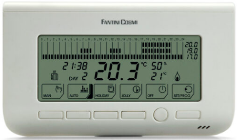
Fantini cosmi CH130ARR Fan-coil Room Thermostat
Introduction
CH130A model is a fan-coil 4- or 2-pipe thermostat that allows you to control the ambient temperature both in the heating and cooling modes. Is able to drive one or two valves and also control a 3-speed fan-coil motor, either in manual or automatic mode. CH130ARR has a separate activation unit with a two-wire connection, while the CH130ARFR model has the separate activation unit which communicates via radio frequency (wireless).
Dimension
KIT COMPOSITION TABLE

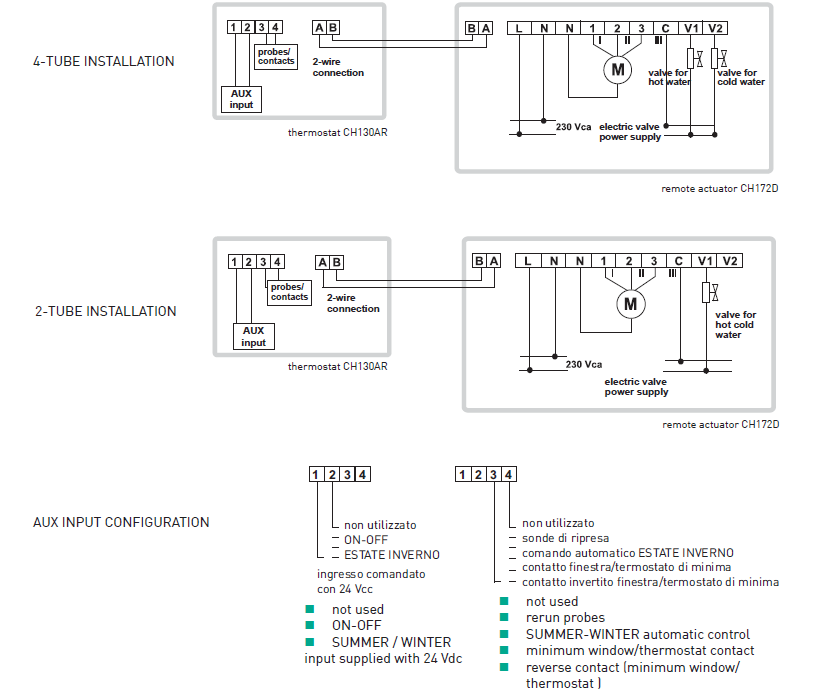
Wiring Diagram
CH130ARRWire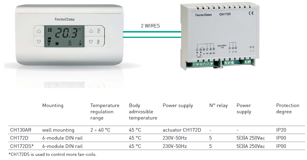
CH130ARFR

ELECTRICAL FEATURES
CH130ARRWire
- Power supply from a remote actuator.
- Remote actuator with 5 output relays, voltage 250 Vac.
- Contacts rating 5(3)A.
CH130ARFR
- Power supply from 2 AA type batteries of 1,5V.
- Remote actuator with 5 output relays, voltage 250 Vac.
- Contacts rating 5(3)A.
4-TUBE INSTALLATION

2-TUBE INSTALLATION 
AUX INPUT CONFIGURATION

HOMOLOGATION AND STANDARDS
- Complies with EN 60730-2-9 standards
- ErP: ErP Class IV; 2% (Reg. EU 811/2013 -813/2013)
INSTALLATION
The thermostat is supplied complete with a base suitable for mounting on the wall, as well in rectangular or round built-in 3-seat boxes.
OPERATION
CH130ARR is supplied from the actuator and is able to drive two valves and also control a 3-speed fan-coil motor. CH130ARFR is supplied with two AA batteries of 1,5V and is able to drive two valves and also control a 3-speed fan-coil motor by means of CH172DRF actuator. The wide display shows the measured temperature, fan speed, the running program and the selected season. The settings and data are stored in a permanent (nonvolatile) memory capable of keeping them even in the absence of power supply or when the batteries are not inserted (according to the model
SUMMER/WINTER SELECTION
To switch from the “Winter” operation (i.e. heating system) to the “Summer” operation (i.e. cooling system), and vice versa, press the 1+2 button combination. The selected operation mode will be indicated on the display by the “Winter” or “Summer” icons.
BUTTONS COMBINATIONS
- 1 fan speed increase button, at the maximum prescribed speed is configured the “AUTO” operating mode.
- 2 fan speed decrease button, exits the “AUTO” mode and decreases the fan speed.
- 1+2 SUMMER/WINTER switch.
- 3 temperature value increase button for the selected program.
- 2+4 Celsius/Fahrenheit switch.
- 3+4 COMFORT/ECONOMY switch.
- 4 temperature value decrease button for the selected program.
- 5 thermostat reset button.
VISUALIZATION (SIGNALS)
- measured temperature
- COMFORT symbol
- ECONOMY symbol
- SUMMER symbol
- WINTER symbol
- fan speed symbol

OPERATING MODES
CH130… thermostats have 3 different operating modes:
- With the COMFORT operating mode, the thermostat regulates the heating or cooling installation operation in order to always keep the same prescribed comfort temperature.
- With the ECONOMY operating mode, the thermostat regulates the heating or cooling installation operation in order to always keep the same prescribed economy temperature.
- (OFF) function can be achieved by setting the fan speed to zero. In this case, the thermostat does not perform the regulation. The system will switch OFF completely and on display will appear the message “OFF”.
FAN SPEED SELECTION
- MANUAL: fan speed can be set manually to free fixed levels (minimum, medium, maximum).
- AUTO: if the speed is set in Auto, the thermostat sets automatically the appropriate speed according to the difference between the set-point and the ambient temperature.
- CH130A thermostat has available a TECHNICAL MENU for adapting to different system types.
TECHNICAL MENU SYSTEM TYPE
- 2-tube system: the thermostat will drive only the valve (ON/OFF type) used for heating both during the heating and the cooling; in fact, the valve will control both hot water and cold water.
- 4-tube system: the thermostat will drive one valve (ON/OFF type) used for heating, plus one additional valve (ON/OFF type) used for cooling, based on the needs of the environment.
EXTERNAL PROBE
- RESUMPTION: instead of the probe incorporated into the thermostat, an external probe can be used to read the ambient temperature and carry out heat regulation. Typically, this probe will be positioned under the fan-coil where air is sucked.
- CHANGEOVER: the external temperature probe can be placed on the fan-coil delivery tube of a 2-tube system to perform automatic changeover between the “Summer” operation and the “Winter” operation.
- MINIMUM WINDOW/THERMOSTAT CONTACT: when the contact is open, the thermostat will carry out heat regulation; when it is closed, the heat regulation will not be carried out.
- INVERTED MINIMUM WINDOW/THERMOSTAT CONTACT: the window contact will operate with an inverted logic with respect to the statements made in previous step 3.
- NONE: the external probe input will not be controlled by the thermostat.
DISPLAY VISUALIZATION
- AMBIENT TEMPERATURE: the ambient temperature will be shown on the display.
- SET-POINT: the current set point will be shown on the display.
CENTRAL INPUT CONFIGURATION
- ON/OFF: in the event that several thermostats have been installed, you may decide either to drive all of them in the normal operation condition (ON) or taking advantage of the OFF function by controlling them through a central point. The thermostat will be configured to
- OFF when the input is powered with 24 V (d.c. with no polarity obligation or a.c.); on the contrary, it will remain active when the input is free from voltage.
- SUMMER/WINTER: as in the previous case, the thermostat will be configured to “Summer” mode when the input is powered with 24 V; on the contrary, it will remain active in the “Winter” mode when the input is free from voltage.
- NONE: the thermostat will not carry out any operation, whatever the input status.
SUMMER VALVE TYPE
- NORMALLY OPEN: in this case, the water flow is normally open and will be closed when the valve is supplied.
- NORMALLY CLOSED: when the valve is energized, it will open the water flow.
WINTER VALVE TYPE
- NORMALLY OPEN: in this case, the water flow is normally open and will be closed when the valve is supplied.
- NORMALLY CLOSED: when the valve is energized, it will open the water flow.
AMBIENT TEMPERATURE CORRECTION
It can be adjusted from –4.0 to 4.0°C. This parameter is used to correct the acquired ambient temperature. In fact, in some installations, the ambient temperature reading may not be satisfying, due to the probe location (i.e. internal or resumption). With this parameter, a constant value upon reading can be added to or subtracted from.
“WINTER” LOWER LIMIT SET-POINT TEMPERATURE
It can be adjusted from 2.0 to 40.0°C. It represents the lower limit for all the set-points (Comfort and Economy) in the heating mode.
WINTER” UPPER LIMIT SET-POINT TEMPERATURE
It can be adjusted from 2.0 to 40.0°C. It represents the upper limit for all the set-points (Comfort and Economy) in the heating mode.
“SUMMER” LOWER LIMIT SET-POINT TEMPERATURE
It can be adjusted from 2.0 to 40.0°C. It represents the lower limit for all the set-points (Comfort and Economy) in the cooling mode.
“SUMMER” UPPER LIMIT SET-POINT TEMPERATURE
It can be adjusted from 2.0 to 40.0°C. It represents the upper limit for all the set-points (Comfort and Economy) in the cooling mode.
CHANGEOVER LOWER THRESHOLD
It can be adjusted from 0 to 24°C. It defines the changeover function lower threshold. Below this temperature, the thermostat will be set to the cooling mode.
CHANGEOVER UPPER THRESHOLD
- It can be adjusted from 26 to 48°C. It defines the changeover function upper threshold. Above this temperature, the thermostat will be set to the heating mode.
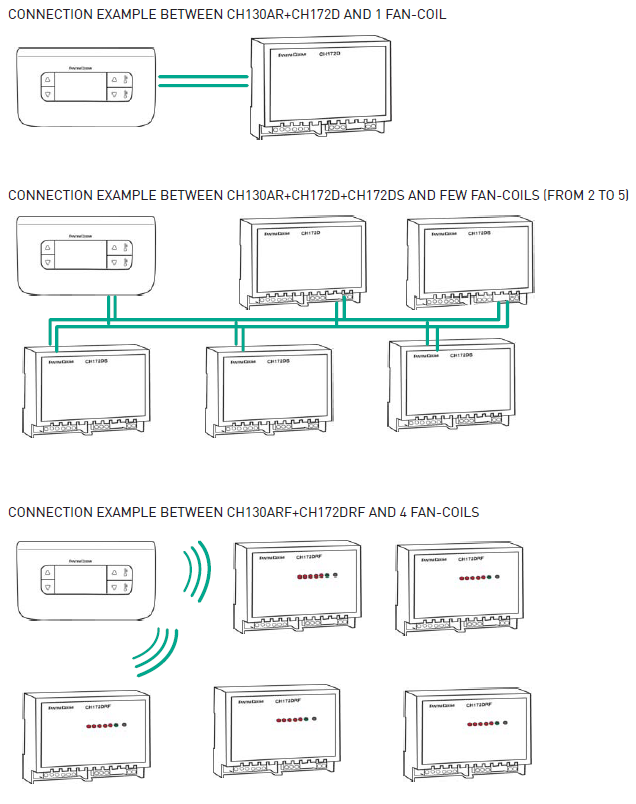
- CH130ARR can control up to 5 fan-coil units simultaneously, using only two cables for connecting to the actuators.
- One of these actuators must be a CH172D, while others, maximum four, will be CH172DS.
- A CH130ARFR can control an unlimited number of actuators provided that they are located within reception range of 30 meters.
FEATURES
- Auxiliary input for minimum window and/or thermostat contact using an external probe.
- Screwed terminals.
- double insulation.
- Dimensions 135 X 83 X 21 mm.
REFERENCE:
DOWNLOAD MANUALS:
Fantini cosmi CH130ARR Fan-coil Room Thermostat Product Data Sheet
OTHER MANUALS:
Fantini cosmi CH130ARR Fan-coil Room Thermostat Instruction Manual
![]()
Fantini cosmi CH130ARR Fan-coil Room Thermostat Product Data Sheet
Leave a Reply