
Fantini cosmi CH130RFR Fan-coil Room Thermostat
Introduction
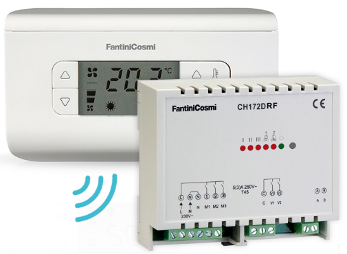
This fan-coil thermostat control kit CH130RFR is made up of a CH130RF thermostat and a DIN bar CH172DRF actuator. The CH130RF model is a fan-coil 4- or 2-pipe thermostat that allows you to control the ambient temperature both in the heating and cooling modes. These controls are sent to a CH172DRF actuator that communicates with the CH130RF through radio frequencies. The CH130RF is powered by two AA-size batteries (1.5 V). It is able to drive two valves and control a 3-speed fan-coil motor, in manual mode. The thermostat measures the ambient temperature either through an internal probe or an external sensor. It keeps the set point by acting on the ventilation speed. The wide display shows the measured temperature, the fan speed, the program being run and the selected season. The settings and data are stored in a permanent memory capable of keeping the same even when the batteries are not inserted
Controls and signals
Controls
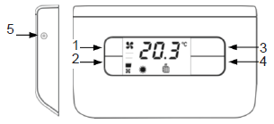
- Fan speed increase button
- Fan speed decrease button
- Selected program temperature value increase button
- Selected program temperature value decrease button
- Thermostat reset button
Button combinations (press simultan.)
- 1+2 Summer/Winter switch
- 3+4 Comfort/Economy switch
- 2+4 Celsius/Fahreneit switch
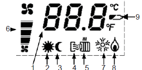
Signals
- Measured temperature
- “Comfort” symbol
- “Economy” symbol
- “Summer” symbol
- “Winter” symbol
- Fan speed symbols
- System “ON” in summer operation
- System “ON” in winter operation
- Low battery charge
User’s manual
First of all, make sure that the self-learning procedure has already been performed (page 8); moreover, verify that both the CH130 and the CH172D are 30 meters far from each other at the most. In fact, this distance represents the free air maximum range for the radio frequency modules used by the thermostat and the actuator. Please note that the range will decrease if obstacles are found between the CH130RF and the CH172DRF.
To start the thermostat after the same has been installed, proceed as follows:
- Select the Summer / Winter operation;
- Select the operating mode;
- Select the fan speed.
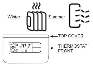
Summer / Winter” selection
To switch from the “Winter” operation (i.e. heating system) to the “Summer” operation (i.e. cooling system), and vice versa, press the 1+2 button combination. The selected operation will be indicated on the display by the “Winter” or “Summer” icons.
Operating modes
The CH130RF thermostat features three different manual operating modes: “Comfort”, “Economy”, and the “OFF” function (OFF).
“Comfort” operating mode
With the “Comfort” operating mode, the thermostat regulates the heating or cooling system operation in order to always keep the same comfort temperature set. To switch from “Economy” to “Comfort”, press buttons “3” and “4” simultaneously.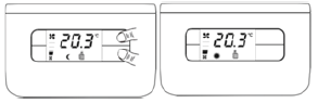
The temperature level can be modified during operation by means of buttons “3” and “4”. The temperature can be changed from 2°C to 40°C by 0.1°C steps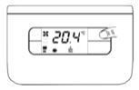
Economy” operating mode
With the “Economy” operating mode, the thermostat regulates the heating or cooling system operation in order to always keep the same economy temperature set. To switch from “Comfort” to “Economy”, press buttons “3” and “4” simultaneously.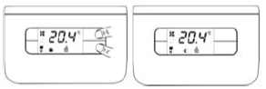
The temperature level can be modified during operation by means of buttons “3” and “4”. The temperature can be changed from 2°C to 40°C by 0.1°C steps
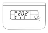
“OFF” function (OFF)
The “OFF” function can be achieved by setting the fan speed to zero: in this case, the thermostat will carry out no heat regulation, not even the antifreeze one. The system will switch off automatically, and the “OFF” message will appear on the display.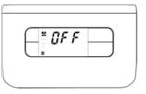
Fan speed selection
The fan speed can be set either to three fixed levels (minimum, medium, maximum) by pressing buttons “1” and “2”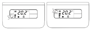
Maintenance
The thermostat should be cleaned by using a soft cotton cloth. No detergent should be used.
Installation
Warning! The thermostat shall be installed only by qualified personnel, in strict compliance with the law regulations in force.
The thermostat installation involves carrying out the following operations:
- Fastening the socket;
- Making the electric connections;
- Fastening the thermostat onto the socket;
- Inserting and replacing the batteries;
- Configuring the thermostat parameters.
Fastening the socket
The thermostat is supplied complete with a socket suitable for mounting both on the wall and to rectangular or round built-in 3-seat boxes (503).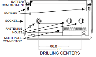
Remove the thermostat top cover. Separate the thermostat socket and front by removing the screw by means of a suitable tool and taking the front part off. Fasten the socket to the desired surface by means of the special fastening holes; make sure that the socket is properly engaged, with no deformation, and that the connecting multipole connector is located in the right bottom corner. To ensure correct operation, the socket shall be placed at a height of approximately 1.5 metres from the fl oor, far from heat sources (direct sunlight, etc.) and doors/windows.
Electric connections
Connect the two external probe wires with screwed terminals “1” and “2”, as illustrated in the figure. Such probes can be configured as an external probe or minimum temperature contact. See the “thermostat configuration” paragraph, P02 parameter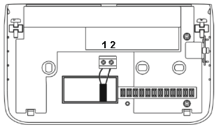
Fastening the thermostat onto the socket
Insert and screw the thermostat down to the socket (make sure that the multi-pole connector is engaged correctly).
Inserting and replacing the batteries
- Insert two “AA” batteries (1.5 V) into the battery compartment, according to the correct polarity: the negative pole shall press the metal spring (located on the right, when viewing the thermostat from the front). Fit the battery top cover back into place.
- A pair of new batteries will normally last one year at least. WHEN THE “low battery charge” SYMBOL APPEARS ON THE DISPLAY, BOTH BATTERIES SHALL BE REPLACED.
CH172DRF self-learning procedure
In order for the CH130RF and the CH172DRF to be able to communicate correctly, a “self-learning” procedure shall be performed. During this procedure, the remote actuator will recognize and store the CH130RF identity: from now on, it will be able to perform all of its controls while leaving out the controls from other transmitters that might be found in the area (please note that the CH130RF/CH172DRF system range is approximately 30 meters in the free air).
To perform self-learning, proceed as follows:
keep the CH172DRF button depressed for at least 5 seconds, until the multicolor LED comes on by switching between green, yellow, red, and OFF. Then press the CH130RF reset button: after a few instants, the LED will be blinking fast and then illuminate green steadily, to indicate that the self-learning has occurred (this procedure is also described in the CH172- DRF instruction sheet).
N.B. You can also control two or several CH172DRF actuators by means of one single CH130RF: of course, the self-learning procedure shall be performed on all the CH172DRFs (it shall not necessarily be performed at the same time).
Thermostat configuration
The thermostat configuration allows you to customize the device operation parameters.
To access the configuration program, proceed as follows:
- Press the “Reset” button and also button “3” (with the thermostat ON);
- Release the “Reset” button, then keep button “3” depressed for at least 3 seconds.
- Release button “3”.
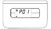
The configuration parameters are represented by an index (P01, P02…) on the display; bypressing buttons “1” and “2”, the parameter indexes will be scrolled through. Press button “3” to enter the displayed parameter. To modify the current parameter, press buttons “1” and “2”. To exit the parameter, press button “3”. Once all parameters have been set, press button “1” until the “END” message appears, then press button “3”. Now the thermostat will save the modifi ed parameters into the internal memory and will automatically exit the parameter menu. On the contrary, if buttons “1” and “4” are pressed simultaneously when the “END” message is displayed, the CH130RF’s RF address will be reset and the self-learning procedure shall be performed again.
N.B. The thermostat will send the switch-on/-off controls for the three fans and the two valves to the actuator to a fi xed rate of 1 minute.
| Index | Parameter | Values | Preset |
| P01 | Type of system | 1-2 | 1 |
| P02 | External probe | 3-4-5 | 5 |
| P03 | Display visualization | 1-2 | 1 |
| P07 | Ambient tem- perature correction | -4°C –+ 4°C
(step 0.1°C) |
0 |
| P08 | “Winter” lower limit set-point temperature | 2 °C – 40 °C
(step 1°C) |
2.0 °C |
| P09 | “Winter” upper limit set-point temperature | 2 °C – 40 °C
(step 1°C) |
40.0 °C |
| P10 | “Summer” lower limit set-point temperature | 2 °C – 40 °C
(step 1°C) |
5.0 °C |
| P11 | “Summer” upper limit set-point temperature | 2 °C – 40 °C
(step 1°C) |
30.0 °C |
| P14 | Differential adjustment | ±0.3 – ±2°C | ±0.3 °C |
| END | Thermostat saving and reset |
P01: Type of system
- two-tube system: the thermostat will drive only the valve (ON/OFF type) used for heating both during the heating and the cooling: in fact, the valve will control both hot water and cold water.
- four-tube system: the thermostat will drive one valve (ON/OFF type) used for heating, plus one additional valve (ON/OFF type) used for cooling, depending on the needs of the environment.
P02: External probe.
- not available with this version.
- not available with this version.
- minimum window/thermostat contact: when the contact is open, the thermostat will carry out heat regulation; when it is closed, the heat regulation will not be carried out.
- inverted minimum window/thermostat contact: the window contact will operate with an inverted logic with respect to the statements made in previous step 3.
- none: the external probe input will not be controlled by the thermostat.
P03: display visualization
1 ambient temperature: the ambient temperature will be shown on the display. 2 set-point: the current set point will be shown on the display.
P07: ambient temperature correction
It can be adjusted from –4.0 to 4.0°C. This parameter is used to correct the acquired ambient temperature. As a matter of fact, the ambient temperature reading may, on some installations, not be satisfying, owing to the probe location (i.e. internal or resumption). With this parameter, a constant value upon reading can be added to or subtracted from.
P08: “Winter” lower limit set-point temperature
It can be adjusted from 2.0 to 40.0°C. It represents the lower limit for all the set points (“Comfort” and “Economy”) in the heating mode.
P09: “Winter” upper limit set-point temperature
It can be adjusted from 2.0 to 40.0°C. It represents the upper limit for all the set points (“Comfort” and “Economy”) in the heating mode.
P10: “Summer” lower limit set-point temperature
It can be adjusted from 2.0 to 40.0°C. It represents the lower limit for all the set points (“Comfort” and “Economy”) in the cooling mode.
P11: “Summer” upper limit set-point temperature
It can be adjusted from 2.0 to 40.0°C. It represents the upper limit for all the set points (“Comfort” and “Economy”) in the cooling mode.
P14: differential adjustment
It can be set starting from ±0.3°C (value suitable for slow-inertia systems) to ±2°C (value suitable for very reactive systems).
Technical features of the thermostat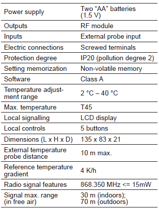
DIN bar CH172DRF actuator
Application and use
An unlimited number of actuators can, if necessary, be controlled by one single thermostat, provided that such actuators are subjected to self-learning and are placed within the maximum communication distance (see below).
Fastening and connecting
- The unit has been designed to be built in (inside fan-coils, special panels or other suitable housings).
- The unit shall be installed by qualified personnel in accordance with the EN regulations in force.
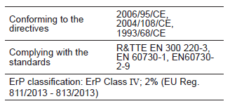
- The maximum communication distance between the actuator and the transmitter shall be 30 m. in free air. Connect the wires to the socket terminal block in accordance with the diagrams illustrated below.
- If a two-tube system is available, connect only valve “1” (contact between terminals “C” and “V1”). In the case of a four-tube system, valve “1” is dedicated to heating, whereas valve “2” (between “C” and “V2”) is dedicated to cooling.
WARNING! Prior to carrying out any operation on the unit, make sure that you have disconnected the main connecting cables.
Operation
The unit operating status is indicated by the LED represented by ![]()
- GREEN: good RF signal level.
- YELLOW: poor RF signal level.
- RED: low or poor RF signal level, or signal not detected.
- Alternating GREEN/RED: relay switch-on manual mode.
- Alternating GREEN/YELLOW/RED/OFF: signal self-learning mode.
- Five more red LEDs indicate the switch-on of the corresponding relays.
To be able to use the CH172DRF with a CH130RF, a self-learning procedure shall be performed: keep the CH172DRF button depressed for approximately 5 seconds until the multicolour LED comes on by switching among green, yellow, red and OFF. Then press the CH130RF reset button: after a few instants, the LED will be blinking fast and then illuminate green steadily.
Operation check
- Refer to the preceding instruction manual for the use of the CH130RF thermostat.
- Make sure that the actuator is close enough to the thermostat (30 m, in free air – or less, if obstacles are found).
- Power the actuator by connecting the same with the electric mains.
- Press the CH172DRF button: the LED will switch between the green and red light, to indicate the manual mode. Each time the button is pressed, one or several relays will turn on: this will be indicated by the switch-on of the corresponding red LEDs.
Below is the switch-on sequence:
- 1°- accessing the manual mode and valve “1” switch-on
- 2°- valve “1” switch-on + engine speed 1
- 3°- valve “1” switch-on + engine speed 2
- 4°- valve “1” switch-on + engine speed 3
- 5°- valve “2” switch-on
- 6°- valve “2” switch-on + engine speed 1
- 7°- valve “2” switch-on + engine speed 2
- 8°- valve “2” switch-on + engine speed 3
- 9°- exiting the manual mode.
Perform a self-learning procedure, as described above. Now, the CH172DRF and the CH130RF will be able to communicate. Switch over, on the thermostat, the fan motor speed (3 relays) and the valve control (2 relays), then verify that they have actually switched over.
Electric connections
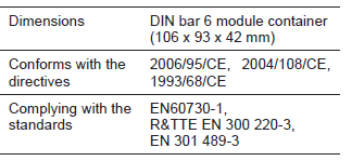
Technical features of the actuator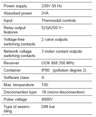
WARNING: SELF-LEARNING PROCEDURE SUPPLEMENT
In case of multiple kits (CH130– plus CH172DRF) installation, proceed as follows:
- Make sure that all CH130 are not powered (battery out).
- Insert batteries in the first CH130–.
- Start self-learning procedure between the CH130– and relevant CH172DRF (as per manual instruction)
- Remove batteries from the fi rst CH130–.
- Repeat the procedure from 1 to 4 for other kits
- When all the self-learning procedures had been done with all kits, insert the batteries in each thermostat and test the heating/cooling system
DISPOSAL OF PRODUCTS
The crossed-out wheeled dust bin symbol indicates that products must be collected and disposed of separately from household waste. Integrated batteries and accumulators can be disposed of with the product. They will be separated at the recycling centres. The black bar indicates that the product was placed on the market after August 13, 2005. By participating in a separate collection of products and batteries, you will help to assure the proper disposal of products and batteries and thus help to prevent potential negative consequences for the environment and human health. For more detailed information about the collection and recycling programs available in your country, please contact your local city office or the shop where you purchased the product.
FANTINI COSMI S.p.A.
- Via dell’Osio, 6 20090 Caleppio di Settala, Milano – ITALY
- Tel. +39 02 956821
- Fax +39 02 95307006
- [email protected]
EXPORT DEPARTMENT
- Ph +39 02 95682229
- [email protected]
REFERENCE
DOWNLOAD MANUALS:
Fantini cosmi CH130RFR Fan-coil Room Thermostat Instruction Manual
OTHER MANUALS:
Fantini cosmi CH130RFR Fan-coil Room Thermostat Product Data Sheet
![]()
Fantini cosmi CH130RFR Fan-coil Room Thermostat Instruction Manual
Leave a Reply