Warmup KW-STATH WIRELESS Thermostat

Instruction
Information about this manual
This manual should be read carefully before commencing operation of your konekt wireless product. Always retain the product manuals for future use.
Symbols used
- Hazard indication
- Important information
Hazard information
- Do not open the device except as instructed to by the installation and operation manual. It does not contain any user-serviceable components.
- The device is suitable for indoor use only. It must not be exposed to moisture, vibrations, mechanical loads or temperatures outside of its rated values.
- For safety and licensing reasons (CE/UKCA), unauthorized change and/or modification of the device is not permitted.
- The device and its packaging are not toys; do not allow children to play with them. Small components such as batteries and packaging preset a risk of choking or suffocation.
- Using the device, in any way or for any purpose, other than those described in their installation and operation manuals invalidates any warranty or liability.
- This device is intended for use in residential, business and commercial properties only.
- Please note that the room temperature control via the radiator thermostat is designed for a two-pipe heating system with one feed and return line per radiator.
- Use in single-pipe heating systems can lead to strong deviations in the set temperature due to fluctuations in the flow temperature.
Function and device overview
The eTRV offers modulating time and temperature control of rooms heated with radiators. It can be used with other devices to create a connected multi-zone system. Use in conjunction with the Thermostat for more accurate temperature regulation. The eTRV fits to all common radiator valves and is easy to mount – without having to drain any water from the heating system.
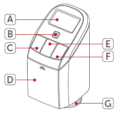
Device overview
- (A) Display
- (B) System button (Pairing button and LED)
- (C) Minus button
- (D) Battery cover
- (E) Menu/Boost button
- (F) Plus button
- (G) Union nut
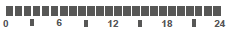 Overview of heating phases
 Setpoint temperature
 Time and date
 Operating lock
 Open window symbol
 Radio transmission
 Low battery
 Holiday mode
 Schedule mode
 Manual mode
 Boost mode
 Offset temperature
 Programming a heating schedule
 Days of the week
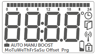
General system information
The eTRV is part of the Warmup konekt Wireless System. Devices in the konekt Wireless System system can be easily paired and setup through the konekt Wireless Smart Hub using the konekt App. All functions of the konekt Wireless System are described in detail in the User Guide. The User Guide and Online manuals for all other konekt Wireless devices are available on www.warmup.co.uk
Start-up
Pairing device
The eTRV can be paired seamlessly to the konekt Wireless Smart Hub (KW-UKHUB). To pair devices to the Smart Hub please download the konekt app.
Pairing to the Smart Hub
The Smart Hub must be set up via the konekt App, before any other devices can be added to your system. For further information, refer to the Smart Hub operating manual.
If you have already connected the eTRV to another konekt Wireless device, you MUST restore its factory settings first before you can connect it to the Smart Hub (see section 9)
- Step 1 – Select Pairing from the konekt App
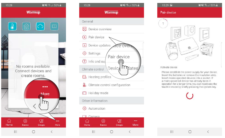
- Step 2 – Remove insulation strip & insert batteries
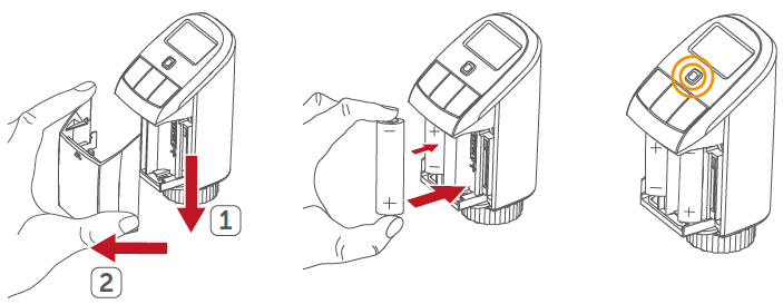
Your device will automatically appear in the konekt App. To confirm, scan the QR code attached to the device or alternatively enter the last four digits of the device number (SGTIN) in the App. Give the device a name and allocate it to a room.
NOTE:
- If pairing was successful, the LED (B) will turn green. The device is now ready for use. If the LED turns red you will have to try pairing the device again.
- You can manually start pairing mode for another 3 minutes by pressing the system button (B) once.
- Once the eTRV has successfully paired to the Smart Hub, programming of the device or changes to device settings must be done through the konekt app.
- If required, you can quickly switch between manual or program mode on the eTRV by pressing and holding the Menu/Boost button (E) for 2 seconds.
Mounting
The eTRV is easy to install and can be done without draining the heating system as long as you have radiators with a suitable radiator valve. The union nut (G) on the eTRV can be directly attached to all valves with a standard thread size of M30 x 1.5.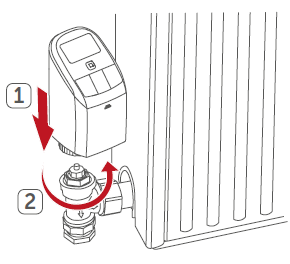
Danfoss RA adapter
The adapter provided is required to attach the eTRV to Danfoss RA valves. The RA adapter is pre-tensioned in order to provide a better fit. If necessary use a screwdriver to open the adapter slightly. The Danfoss valve bodies have elongated notches around their circumference, which also ensure that the adapter is properly seated when it snaps on.
During installation, ensure that the pins inside the adapter are lined up with the notches on the valve. Ensure that a suitable adapter for the valve is properly clipped on. After clipping onto the valve body, attach the adapter using the provided screw and nut.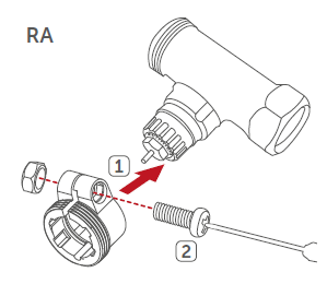
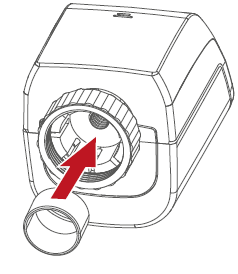
Support ring
The valves from different manufacturers may have tolerance fluctuations that make the eTRV sit more loosely on the valve. In this instance, insert the provided support ring into the flange before mounting.
Adaption run
- Once the batteries are inserted, the motor will automatically start. “InS” and the activity symbol ( ) will appear on the display.
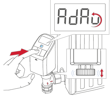
- After the eTRV has been mounted successfully, an adaption run (AdA) has to be performed in order to adapt the device to the valve:
- While “AdA” is displayed, press the menu/boost button (E) to start the adaption run.
- “AdA” and the activity symbol ( ) will displayed. During this time, no other operation is possible. After the adaption run has been successful, the display will return to normal.
- If the adaption run has been initiated prior to mounting or if an error message (F1, F2, F3) is displayed, press the menu/boost button (E) and the motor will return to the “InS” position.
Configuration
Automatic operation
In automatic mode, the temperature is controlled in accordance with your set heating schedule. Any manual overrides will be activate until the next change in the heating schedule.
Manual operation
In manual mode, you can adjust the target temperature you would like eTRV to achieve. The target temperature can be set manually using the Plus/Minus buttons on the eTRV or through the app. This temperature remains active until the next manual change.
Holiday Mode
Holiday mode allows you to maintain a constant temperature for a certain period, e.g. during your holidays.
Operating lock
Operation of the device can be locked to prevent settings being changed.
Offset Temperature
As the temperature is measured on the eTRV, the temperature distribution can vary throughout a room. To adjust this, a temperature offset of ±3.5°C can be set. If a nominal temperature of e.g. 20 °C is set but the room only reaches 18°C, an offset of -2.0°C may need to be set.
Boost Function
This will fully open the radiator valves of any eTRVs assigned to the same room to quickly heat the room. The boost will last for 5 minutes and can be activated by pressing the menu/boost button (E) or through the app.
Through the app you can amend the boost duration from 5 – 30 mins.
Replacing batteries
If the symbol for low batteries ( ) appear in the display or in the app, replace with two new LR6/mignon/AA batteries. Once the batteries have been inserted, the eTRV will perform a self-test and an adaption run. The LED will indicate that initialisation is complete by lighting up orange and then green.
Caution!
- There is a risk of explosion if the battery is not replaced correctly.
- Replace only with the same or equivalent type.
- Never recharge non-rechargeable batteries.
- Do not throw the batteries into a fire.
- Do not expose batteries to excessive heat.
- Do not short-circuit batteries.
- Doing so will present a risk of explosion.
- Used batteries should not be disposed of with regular domestic waste
- Take them to your local battery disposal point.
Troubleshooting
Low batteries
Provided there is enough voltage, the eTRV will still operate. Depending on the load, it may still be possible to send commands. If the voltage drops too far during a command, the low battery symbol ( ) and error code will be displayed on the device (see section 8.4). In this instance, the batteries must be replaced.
Command not confirmed
If at least one device does not accept a command, the LED (B) will light up red. This may be caused by radio interference (see section 11). Other possible issues may be:
- Device cannot be reached.
- Device is unable to execute the command (load failure, mechanical block, etc.).
- Device is defective.
Duty cycle
The duty cycle is a legally regulated limit of the transmission time of devices in the 868 MHz range. The aim of this regulation is to safeguard the operation of all devices working in the 868 MHz range. In the 868 MHz frequency range we use, the maximum transmission time of any device is 1% of an hour (i.e. 36 seconds in an hour). Devices must cease transmission when they reach the 1% limit until this time restriction comes to an end. Warmup devices are designed and produced with 100% conformity to this regulation. During normal operation, the duty cycle is not usually reached. However, intensively repeated device pairing processes may mean that this limit is reached in isolated instances during commissioning.
IMPORTANT: If the duty cycle limit is exceeded, the device may stop working for a brief period. The device will start working normally again after a short period (max. 1 hour).
Error codes and flashing sequences
| Flashing code | Meaning | Solution |
| F1 | Valve drive slow | Check whether the valve pin is stuck. |
| F2 | Actuating range too wide | Check the fastening of the eTRV |
| F3 | Adjustment range too small | Check whether the valve pin is stuck. |
| Battery symbol ( ) | Battery low | Replace the eTRV batteries |
| Battery symbol ( ) and — | Valve moved to error position* | Replace the eTRV batteries |
| *If batteries are not replaced, the eTRV valve will move to a “valve error position”. This means the target temperature in the room cannot be reached due to a low battery. A valve error position of 15 % open is set in the factory settings. | ||
| Antenna symbol ( ) flashing | Communication problem with SmartHub or connected device | Check the connection with the SmartHub or the connected devices. |
| Lock symbol ( ) | Operating lock activated | Deactivate the operating lock in the app. |
| Short orange
flashing |
Radio transmission/ attempting to transmit/ configuration data is transmitted | Wait until the transmission is completed. |
| 1x long green light | Transmission confirmed | You can continue operation. |
| 1x long red light | Transmission failed or duty cycle limit is reached | Please try again |
| Short orange flashing (every 10 s) | Pairing mode active | Enter the last four numbers of the device serial number to confirm |
| Fast orange
flashing |
Pairing mode active | Activate the pairing mode of the device you want to pair |
| Short orange light (after green or red confirmation) | Batteries empty | Replace the batteries |
| 6x long red
flashing |
Device defective | Have a look at your app for error message or contact Warmup. |
| 1x orange and 1 x green lighting (after inserting batteries) | Test display | Once the test display has stopped, you can continue. |
| Long and short orange flashing (alternating) | Update of device software | Wait until the update is completed. |
Restore factory settings
The factory settings of the device can be restored. The device will automatically reconnect to the system and redownload its settings unless it is deleted within the konekt App first.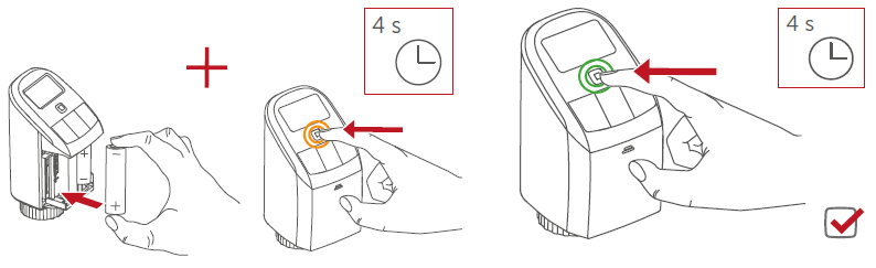
- Open the battery compartment.
- Remove a battery.
- Re-insert the battery while pressing and holding the system button (B) until the device LED (B) starts to flash orange
- Release the system button and then press and hold the system button (B) again until the orange flashing changes to green.
- Release the system button (B) to finish.
Maintenance and Cleaning
The device does not require any specific maintenance other than replacing the battery when necessary. To clean, use a soft, clean and lint-free cloth. To remove more stubborn marks, dampen the cloth with warm water. Do not use detergents or chemicals on the devices.
General information about radio operation
Radio transmission is performed on a non-exclusive RF channel, which means that there is a possibility of interference occurring. Interference can also be caused by switching operations, electrical motors or defective electrical devices.
The range of transmission within buildings can differ greatly from that available in the open air. Besides the transmitting power and the reception characteristics of the receiver, environmental factors such as humidity in the vicinity have an important role to play, as do on-site structural/screening conditions.
Declaration of Conformity
Warmup hereby declares that the Warmup konekt Wireless radio equipment is compliant with RED Directive 2014/53/EU and Radio Equipment Regulations 2017. Please scan the QR Code for the Declaration of Conformity.
Instructions for Disposal
Do not dispose of the device(s) with regular domestic waste! Electronic equipment must be disposed of at local collection points for waste electronic equipment in compliance with the Waste Electrical and Electronic Equipment Directive.
Technical specifications
| Warmup konekt Wireless eTRV | |
| Product Code | KW-UKETRV |
| Supply voltage | 2x 1.5 V LR6/mignon/AA |
| Current consumption | 100 mA max. |
| Battery life | 2 years (typ.) |
| IP Rating | IP20 |
| Ambient temperature | 0 to 50 °C |
| Dimensions (W x H x D) | 56 x 115 x 67 mm |
| Weight | 180 g (incl. batteries) |
| Radio frequency band | 868.0-868.6 MHz, 869.4-869.65 MHz |
| Maximum radiated power | 10 dBm |
| Receiver category | SRD category 2 |
| Typ. open area RF range | 250 m |
| Duty cycle | < 1 % per h/< 10 % per h |
| Software class | Class A |
| Method of operation | Type 1 |
| Degree of pollution | 2 |
| Valve Connection | M30 x 1.5 mm |
Warranty
Warmup plc warrants theses product(s), to be free from defects in the workmanship or materials, under normal use and service, for a period of three (3) years from the date of purchase by the consumer. If at any time during the warranty period the product is determined to be defective, Warmup shall repair or replace it, at Warmup’s option. If the product is defective, please either; Return it, with a bill of sale or other dated proof of purchase, to the place from which you purchased it, or Contact Warmup. Warmup will determine whether the product should be returned or replaced. This warranty does not cover removal or re-installation costs and shall not apply if it is shown by Warmup that the defect or malfunction was caused by failure to follow the instruction manuals, incorrect installation or damage which occurred while the product was in the possession of a consumer. Warmup’s sole responsibility shall be to repair or replace the product within the terms stated above.
WARMUP SHALL NOT BE LIABLE FOR ANY LOSS OR DAMAGE OF ANY KIND, INCLUDING ANY INCIDENTAL OR CONSEQUENTIAL DAMAGES RESULTING, DIRECTLY OR INDIRECTLY, FROM ANY BREACH OF ANY WARRANTY, EXPRESS OR IMPLIED, OR ANY OTHER FAILURE OF THIS PRODUCT. THIS WARRANTY IS THE ONLY EXPRESS WARRANTY WARMUP MAKES ON THIS PRODUCT. THE DURATION OF ANY IMPLIED WARRANTIES, INCLUDING THE WARRANTIES OF MERCHANTABILITY AND FITNESS FOR A PARTICULAR PURPOSE, IS HEREBY LIMITED TO THE THREE-YEAR DURATION OF THIS WARRANTY.
This Warranty does not affect your statutory rights.
Warmup plc
- www.warmup.co.uk
- [email protected]
- Tel: 0345 345 2288
- Fax: 0345 345 2299
REFERENCE:
DOWNLOAD MANUALS:
Warmup KW-STATH WIRELESS Thermostat Installation guide
Other manuals:
Warmup KW-STATH WIRELESS Thermostat Quick start guide
Warmup KW-STATH WIRELESS Thermostat Product Specification Sheet
![]()