
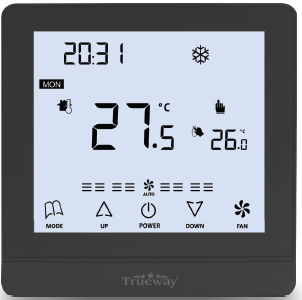
TRUEWAY TX986ML220-V2E TOUCH SCREEN Thermostat
APPLICATIONS
- TX986 series is a fully touch screen thermostat with many variants suitable for 2 pipe/4 pipe cooling & Heating Fan coil units and DX single stage compressor units. We introduce Bacnet and Modbus communication in this series. Option of 9 terminals & 13 terminals power box can occupy addons Like AO, AI, DO and DI as per convenience
- Available in different color body options with sky blue and black backlight. Fitted with a built-in NTC10K sensor and an optional Humidity sensor. Several external functions like remote sensor, key card, PIR sensor, and Light controls are available in different variants as per requirement
FEATURES
- Modern Fully touchscreen design, suitable for offices, Hotels, and residential buildings.
- Modbus R$485 Communicating
- Applicable for 2 pipe/4 pipe fan coil unit cooling & heating.
- Applicable for Dx single-stage compressor Units.
- Black LCD and Sky-blue LCD displays are selectable
- Big LCD with English-only display
- Special colors upon request with
- RAL number can be provided.
- Regular color available in Black, White and Silver body
- User settings can be kept during power off
- Both Room and Setpoint Display
- Manual & Automatic Fan functions
- EC motor variants are available.
- User settings can kept during power off
- Temperature unit C & F
- Fan load 5A resistive and inductive of
- 3A (fan load 8A resistive can provide on request)
- 13 terminal power box fits in 86cm × 86 cm & 9 terminal power box fits in 75cm x 75cm electrical junction box
- Real-Time clock with infinite life battery backup
SPECIFICATION
- Power supply 12v/24v/85-220v based on variants
- Frequency:50^60Hz
- Function: Cooling/Heating
- Relay Life: 220‡10% VAC, 3(5)A, 100,000 times
- Wiring Max: 16AWG
- Sensing Element: 10K(@25°C) NTC
- Display Accuracy: 1°C, Set-point accuracy: 1°C/step
- Set-point range: 10-32°C(50-90°F) • Display range: 0-50°C
- Protection Glass: IP 20 • Operation Temperature: -18~49°C
- Shipping Temperature: -35^65°C Suitable System: 2-pipe / 4-pipe FCU
- Suitable Valve: 2-line/3-line valve • Relative Humidity: 10~90%
- 13 terminal power box fits in 86cm x 86 cm & 9 terminal power box fits in 75cm x 75cm electrical junction box
LCD DISPLAY & KEYS DESCRIPTION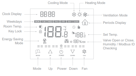
FUNCTION
ORDERING PART NUMBERS
| PART NUMBERS | OPERATING VOLTAGES | APPLICATIONS | VALVE TYPE | ADDON FUNCTIONS |
| TX986ML220-V2E | 85-240VAC | 2-PIPE | 0-10VDC | EXTERNAL SENSOR |
| TX986ML220-V2K | 85-240VAC | 2-PIPE | 0-10VDC | HOTEL KEYCARD |
| TX986ML024-V2E | 24VAC | 2-PIPE | 0-10VDC | EXTERNAL SENSOR |
| TX986ML024-V2K | 24VAC | 2-PIPE | 0-10VDC | HOTEL KEYCARD |
ABBREVIATION
| CASING/COVER COLOR | |
|
BLACK |
B |
|
WHITE |
W |
| BACKLIGHT COLOR | |
|
Sky Blue backlight + Black letters(TN LCD) |
SB |
|
Black backlight + White letters (VA LCD) |
BW |
Operation Instruction
ON-OFF VALVE /COMPRESSOR CONTROL
The thermostat acquires the room temperature via its integrated sensor and maintains the set-point by simple on-off output
POWER ON OR OFF
Pressing the POWER button ![]() to change the power On/Off status
to change the power On/Off status
INCREASE / DECREASE
In the ON state, press ![]() UP or
UP or  DOWN to increase or decrease the setting parameters
HEAT/COOL/VENT
Pressing the MODE button![]() to select heat
to select heat![]() cool
cool![]() or ventilation
or ventilation ![]() mode.
mode.
FAN OPERATION
The fan can be selected as manual or automatic 3-speed operation. In manual mode, the fan will be switched to the selected speed via control output Gh, Gm, Gl (by pressing the FAN button![]() ). In automatic mode, the fan speed will be switched on the difference between the room temperature and the set point. When the room temperature reaches set-point, the valve will be closed and meanwhile, the fan turns to the low-speed fan will be turned off as well “(fan can be changed to low speed instead of turning OFF via ISU mode)”
). In automatic mode, the fan speed will be switched on the difference between the room temperature and the set point. When the room temperature reaches set-point, the valve will be closed and meanwhile, the fan turns to the low-speed fan will be turned off as well “(fan can be changed to low speed instead of turning OFF via ISU mode)”
TEMPERATURE DISPLAY
Both the room temperature and the set point are displayed
COMFORT MODE
In the comfort mode, the set point can be changed by pressing  UP or DOWN buttons. Different applications include cool only, heat only and manual heat/cool changeover
KEY LOCK
The default status of “Key lock” is all keys available and it can be changed in ISU mode. Key lock function includes the following settings: All keys are available (Default) Mode button is locked out. The fan and Mode buttons are locked out. All buttons are locked.
ENERGY SAVING MODE
By pressing the MODE button for 3 seconds can activate the energy-saving mode with an icon
![]() appearing on the screen. If energy saving is activated by the button pressed, pressing the POWER button
appearing on the screen. If energy saving is activated by the button pressed, pressing the POWER button![]() will stop energy saving mode. For heating mode, if the energy-saving function is enabled, the set-point will be changed to a remote setback heating set-point. The range of remote setback heating set-point is from 10 °C to 21 °C and the default value is 18 °C. The value can be changed in ISU mode with the step of 1 °C. For cooling mode, if the energy saving function is enabled, the set-point will be changed to a remote setback cooling set-point. The range of remote setback cooling set-point is from 22°C to 32°C and the default value is 26 °C. The value can be changed in ISU mode with the step of 1 °C.
will stop energy saving mode. For heating mode, if the energy-saving function is enabled, the set-point will be changed to a remote setback heating set-point. The range of remote setback heating set-point is from 10 °C to 21 °C and the default value is 18 °C. The value can be changed in ISU mode with the step of 1 °C. For cooling mode, if the energy saving function is enabled, the set-point will be changed to a remote setback cooling set-point. The range of remote setback cooling set-point is from 22°C to 32°C and the default value is 26 °C. The value can be changed in ISU mode with the step of 1 °C.
FREEZE PROTECTION MODE
Freeze protection can be disabled (default) or enabled via ISU mode. If freeze protection is enabled ( it is not available in the cooling only application) and the thermostat is in OFF mode while the room temperature is below 6 °C, the thermostat will open the heating device before the temperature rises to 8 °C
TIME SETTING
In ON/OFF states, press and for 5 seconds, the time area
![]() will be flashing, press to select minutes, hours or week, then press or to adjust the relevant time, press to confirm
will be flashing, press to select minutes, hours or week, then press or to adjust the relevant time, press to confirm
TO SELECT MANUAL AND PROGRAMMABLE
In the thermostat ON status, Press and hold , and for more than 5 seconds, the icon of  will be flashing, press to select manual or programmable
![]() and press
and press ![]() to confirm.
to confirm.
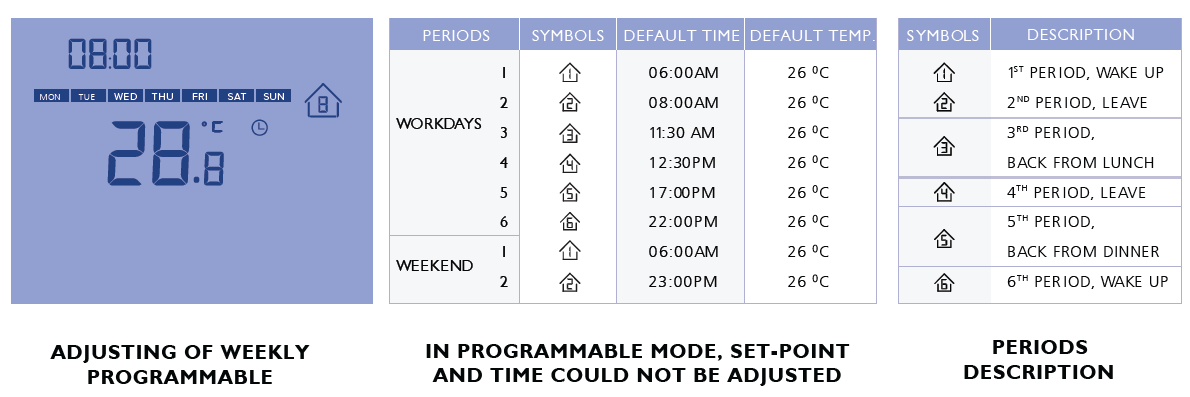
ADJUSTING OF WEEKLY PROGRAMMABLE
After selecting programmable mode, press for more than 5 seconds enters into the program schedule setting then press to select the setting item of periods, time, and temp. Press or to adjust the relevant value, and press to confirm. The program schedule is a weekly (7 days) cycle, it can be selected for 5+2 days, 6+1 days or 7 days. 5+2 is 5 workdays plus 2 days holiday a week, 6+1 is for 6 workdays plus 1 day holiday a week, and 7 is for 7 workdays a week. There are 6 periods for workdays and 2 periods for holidays.
SETUP FUNCTION SETTINGS AND OPTIONS
- Press and key for 5 seconds to enter ISU setting mode, the ISU code will be flashing.
- Press or to select the setting items from 1-26.
- Press and the values of the selected item will be flashing with the icon on,
- Press
 revise the values of the setting items, and press to confirm.
| NO | FUNCTION | SETTING AND OPTIONS | DEFAULT |
|
1 |
SYSTEM TYPE |
0 > Heat only 1 > Cool only
2 > Two pipes 1H1C manual(Default) |
2 |
|
2 |
TEMPERATURE UNIT SETTING |
0 > ° F
1 > ° C |
1 |
|
3 |
FAN CONTROL TYPE |
0 > AUTO ONLY
1 > CONSTANT ONLY 2 > BOTH(DEFAULT) |
2 |
|
4 |
KEY LOCK SETTING |
0 > ALL KEYS ARE AVAILABLE (DEFAULT IS 0 )
1 > SYSYEM BUTTON IS LOCKED OUT 2 > ONLY RESERVED FOR OTHER MODEL SETTING 3 > ALL BUTTONS ARE LOCK OUT |
0 |
|
5 |
N/A |
THIS ITEM IS NOT AVAILABLE(RESERVED FOR OTHER MODEL’S ISU MODE SETTING) |
|
|
6 |
FREEZE PROTECTION |
0 > DISABLED ; 1 > ENABLED |
0 |
|
7 |
DISPLAY TEMP. ADJUSTMENT |
-2 °C(-4°F); -1.5°C(-3°F) -1°C(-2°F) -0.5°C(-1°F) 0°C(0°F), 0.5°C(1°F) 1°C(2°F) 1.5°C(3°F) 2°C( 4°F ) |
0.0 °C (0°F) ) |
|
8 |
REMOTE SETBACK HEATING MODE |
RANGE 10-21°C ( RANGE 50-70°F ) |
18°C( 64°F) |
|
9 |
REMOTE SETBACK COOLING MODE |
RANGE 22-32°C (RANGE 72-90°F |
26°C( 79°F) |
|
10 |
MODBUS ID DISPLAY SETTING |
0 > OFF(NO DISPLAY OF MODBUS ID) ; 1 > ON(DISPLAY) |
0 |
|
11 |
P : ADJUSTMENT OF VALVE CONTROL |
RANGE:1-10 FOR PROPORTIONAL OUTPUT ADJUSTMENT, IT SHOULD BE ADJUSTED BASES ON THE ACTUAL CONDITION |
4 |
|
12 |
I : ADJUSTMENT OF VALVE CONTROL |
RANGE:1-60 INTEGRAL OUTPUT ADJUSTMENT, IT SHOULD BE ADJUSTED BASES ON THE ACTUAL CONDITION |
25 |
|
13 |
SENSOR SELECTION |
0 > INTERNAL SENSOR(BUILT-IN) ; 1 > EXTERNAL SENSOR |
0 |
| 14 | BEE SOUND SETTING | 0 > ON ; 1 > OFF | 1 |
| 15 | PROGRAM SETTING | 0 > 5 WORKING DAYS A WEEK ; 1> 6 WORKING DAYS A WEEK ; 2 > 7 WORKING DAYS A WEEK; 3 > CLOSE THE PROGRAM SCHEDULE; PS: IF YOU SELECTED 7 WORKING DAYS A WEEK, THE WHOLE SCHEDULE IS THE SAME(ONLY 6 PERIODS), IF YOU 5 WORKING DAYS A WEEK, IT WILL HAVE 2 TYPES OF PERIODS FOR THE WEEK, WORKING DAYS 6 PERIODS, AND WEEKEND (HOLIDAYS) IS 2 PERIODS |
0 |
| 16 | MINI. OUTPUT ON/OFF TIME | 0-4 MINUTES, WHEN THE SETTING IS 1, WITH 1 MINUTE DELAY FOR BOTH ON OR OFF THE COMPRESSOR. |
3 |
| 17 | FAN STOP/RUN SETTINGS | 0 > FAN WILL BE SWITCHED TO LOW SPEED WHEN THE VALVE TURNS OFF 1> FAN WILL BE TURNED OFF WHEN THE VALVE TURNS OFF |
0 |
| 18 | ON / OFF BACK-LIGHT SETTING WHEN STANDBY | 0: OFF, THE BACK-LIGHT WILL BE OFF ALWAYS EVEN THE USER PRESSING ANY KEY 1: ON, THE BACK-LIGHT WILL BE ON FOR ABOUT 15 SECONDS IF ANY KEY PRESS |
0 |
| 19 | ON / OFF MEMORY SETTING | 0: OFF, USER SETTING WILL NOT KEEP WHEN POWER OFF (WHILE ELECTRIFIED, THE THERMOSTAT WILL BE OFF) 1: ON, USER SETTING WILL BE KEPT WHEN POWER OFF (WHILE ELECTRIFIED, THE THERMOSTAT WILL BE ON |
0 |
| 20 | BACK-LIGHT SETTINGS | 10-60 SECONDS(USER CAN ADJUST BACK-LIGHT TIME ACCORDINGLY TO ACTUAL DEMANDS) |
15 |
| 21 | VALVE OPEN VALUE SETTING | 0: OFF, THE VALVE OPEN VALUE WILL NOT BE DISPLAYED ON THE LCD 1: ON, THE VALVE OPEN VALUE WILL BE DISPLAY ON LCD (ONLY AVAILABLE FOR MODULATING TYPE THERMOSTAT |
0 |
| 22 | RESERVED FOR ADDITIONAL ISU SETTINGS | ||
| 23 | RESERVED FOR ADDITIONAL ISU SETTINGS | ||
| 24 | RESERVED FOR ADDITIONAL ISU SETTINGS | ||
| 25 | RESERVED FOR ADDITIONAL ISU SETTINGS | ||
| 26 | RESERVED FOR ADDITIONAL ISU SETTINGS |
WIRING DIAGRAM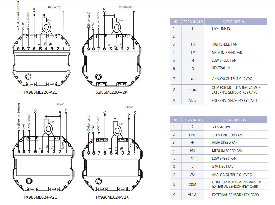
TERMINAL POWER BOX
wiring is subject to change without notice based on addons
DIMENSION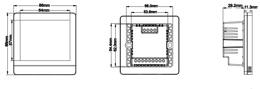
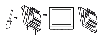
INSTALLATION AND COMMISSIONING
- To take the front panel and back plate apart by screwdriver
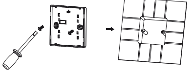
- Wiring on the terminals of the back plate according to above wiring diagram, then fix the back plate on the junction box by screw driver
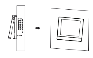
- Recombine the front panel and back plate by contract pins.
Install the thermostat about 5 feet(1.5m) above the floor in an area with good air circulation at average temperature. Do not install in locations where the thermostat can be affected by:
- Drafts or dead spots behind doors and in corners
- Hot or cold air from ducts
- Sunlight or radiant heat from appliances
- Concealed pipes or chimneys
- Unheated/uncooled areas such as an outside wall
TROUBLESHOOTING
| IF… | THEN… |
|
Heating system does not turn on |
Set the mode to Heat by pressing the Mode button. Wait five minutes for the heating system to respond. |
|
Cooling system does not turn on |
Set the mode to Cool by pressing the Mode button. Wait five minutes for the cooling system to respond. |
|
The fan doesn’t work |
Check whether the Fan mode is set to Auto. Check whether the heating or cooling system works well or not. |
|
The Mode button does not work |
Check whether the Keypad is locked or not(ISU setting code 4). Check whether the system is working in Energy saving mode. Check whether the thermostat is of. |
|
The Fan button does not work |
Check whether the Keypad is locked or not(ISU setting code 4). Check whether the system is working in Energy saving mode. Check whether the thermostat is of. |
|
The Up or Down button does not work |
Check whether the Keypad is locked or not(ISU setting code 4). Check whether the system is working in Energy saving mode. Check whether the thermostat is of. |
REFERENCE
DOWNLOAD MANUALS:
TRUEWAY TX986ML220-V2E TOUCH SCREEN Thermostat OPERATION INSTRUCTION
![]()
TRUEWAY TX986ML220-V2E TOUCH SCREEN Thermostat OPERATION INSTRUCTION
Leave a Reply