Lizard CONTROL RS-485 FAN COIL COMMUNICATION THERMOSTAT
SPECIFICATION
- Electrical Rating…………………………100~240VAC 50/60Hz
- Fan Relay Amps inductive……………3A
- Cool Relay Amps inductive…………0.5A
- Set point Temperature Range……………5℃to 35℃
- Ambient temperature operation…………0℃~+50℃
- Ambient temperature-transport………….-10℃~+60 ℃
- Dimensions…………………………86mm×86mm×25mm (or 3.38″×3.38″×0.985″)
- Color………………………………………White
FEATURES
- Large LCD display with backlight
- Temperature adjustments are simple with the large up-down arrows
- Display shows both set points and room temperature simultaneously
- Maintains the temperature to within a 1-degree set point
- Auto fan with adjustable 3-fan speed.
- Permanent user setting retention during power loss, no batteries are required
- Room Sensor or External sensor model option
- Remote control
- With RS485 communication.
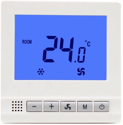
PREPARATION
The Thermostat Buttons and Switches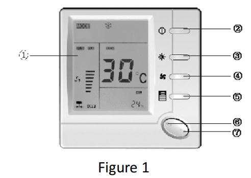
- Display area
- Power button
- System button (COOL, HEAT)
- Fan speed option button (HI MED LOW AUTO)
- leep operation button
- Raises temperature setting
- Lowers temperature setting.
The Display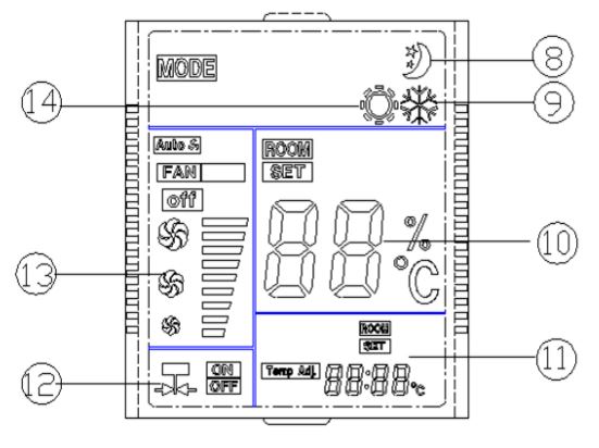
- Shows when thermostat is in sleep operation
- Shows thermostat is in cooling mode
- Always shows room temperature, whilesetting temperature shows set temperature
- Always shows set temperature, while setting temperature shows room temperature.
- Indicate the output to motorized valve is ON or OFF
- Shows fan speed option
- Shows Room Card function active
INSTALL THE THERMOSTAT:
ATTACH THERMOSTAT BASE TO WALL
WARNING: ELECTRICAL SHOCK HAZARD
Turn off power at the main service panel by removing the fuse or switching the appropriate circuit breaker to the OFF position before removing the existing thermostat.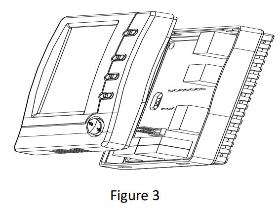
- Remove the packing material from the thermostat. Back cover module wiring
- Junction box embedded in the Back cover
- The screws through the back cover are tightened and fixed
- Gently pull the control panel straight off the back cover. Forcing or prying on the thermostat will cause damage to the unit.
- Installation is finished
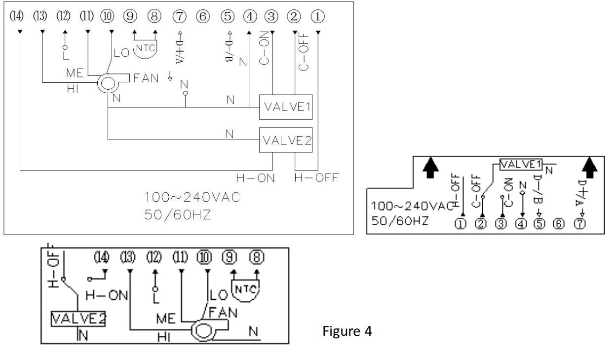
WIRING DIAGRAM
OPERATION
CHECK THERMOSTAT OPERATION: Switch on the thermostat
External temperature sensor function:
When connecting the external temperature sensor, room temperature displays for external temperature, control the outside temperature sensor shall prevail. When there is no connect external temperature sensor with built-in temperature sensor temperature shall prevail.
Fan operation
- PUsh fan button, the display will show
 and Auto separately means fan rotate in HI MED LOW or AUTO speed.
 - If you select AUTO speed, fan operation will change speed according to the difference between the room temperature and set temperature. If room temperature is 3℃higher than setting temperature in cooling or3℃lower than setting temperature in Heating. Fan will run in HI speed. If room temperature is 2℃- 3℃higher than setting temperature in cooling or 2℃-3℃lower than setting temperature in Heating. Fan will run in Medium speed. If room temperature is 0℃-2℃higher than setting temperature in cooling or 0℃-12℃lower than setting temperature in Heating. Fan will run in Low speed.
Heat system operation
- Press the system switch to heat mode (
 )
) - Press “+1” to adjust the thermostat setting above the room temperature. The heating Syste1m should start to operate.
- Press “-” to adjust the thermostat setting below the room temperature. The heating system should stop operating.
Cooling system operation
- Press system switch to cool mode ( )
- Press “-“ to adjust thermostat setting below room temperature. The cooling system should start to operate.
- Press “+” to adjust the temperature setting above room temperature. The cooling system should stop operating
Network communication Communication protocol is standard RS485 protocol connect the upper computer, can control the thermostat temperature and fan speed.
CONFIGURATION
Configuration Menu
The configuration menu allows you to set certain thermostat operating characteristics to your system or personal requirements. Switch off the thermostat and hold the sleep operation Button ○,5 for over 4second till power on again means you have entered the first configuration menu item. There are 6 menu items. Press button ○,5 to change to the next item. Then press the button ○,5or ○,2 to confirm, and exit preferences return to switch off . Switch on the thermostat and press ○,5 to come to the sleep operation . In the off state, press this button more than 4 seconds. You can cycle into the Implicit menu settings; In Implicit menu settings mode, press button ○,5 more than 4 seconds,it will display dEF, flash three times, All the settings back to the initial value.
| Step | Press buttons | Displayed
(factory default) |
Press▲、▼to select | Descriptions |
| 1 | ○ ,5 4
seconds |
01 (0) | -3 — +3 | Adjust temperature coefficient |
| 2 | ○ ,5 | 02(35℃) | 20℃—35℃ | Select maximum setting
temperature for heating |
| 3 | ○ ,5 | 03(5℃) | 5℃—20℃ | Select minimum setting
temperature for cooling |
| 4 | ○ ,5 | 04(rE) | rd, rE | Memorize option before
power loss |
| 5 | ○ ,5 | 05( 1 ) | 1、2、3 | Display backlight option |
| 6 | ○ ,5 | 06 (On) | OFF/On | Fan stop option |
- Select temperature recalibrates Adjustment 3 LO to 3 HI –
You can adjust the room temperature display up to 3 higher or lower. Your thermostat was accurately calibrated at the factory but you have the option to change the display temperature to match your previous thermostat. - Select maximum temperature for heating.
This feature provides a maximum setpoint temperature for heat. The default setting is 35℃, It can be changed between 20℃to 35℃ - select minimum temperature for cooling
This feature provides a minimum setpoint temperature for cooling. The default setting is 5℃, It can be changed between 5℃to 20℃ - Memorize option before power loss
Using ▲ & ▼ button to select between “rE” and “rd”. “rE” means the thermostat will Memorize its ON or OFF status before power loss. After power supply comes to normal again, the thermostat will remain ON or OFF according to what it is before power loss. “rd” means no matter the thermostat is switched on or off before power loss, after the power supply comes to normal again the thermostat will keep power off - display backlight option
Select 1 the light will be on when any button of the thermostat is touched. Select 2 the display will keep the light on continuously. Select 3 the display will keep the light off continuously Factory default is 1 - fan stop option
Using ▲ & ▼ button to select between “On” and “OFF”. If you select “On”, the
thermostat will turn on the fan at a speed provided by the Fan Switch and will not stop the fan when there is no call for heat or cool. If you select “OFF”, the thermostat will stop the fan when there is no call for heat or cool.
Communication address setting
Before entering network debugging, need to set the all thermostats communication address and every thermostat communication address is uniqueness and different, or else, the thermostat communication will be broken-down and stop.
In switch off state, long press button ④over 5 seconds till power on again means you have entered communication address setting, press “+” or “-“ to modify the address, the setting range is 1~255, then press the button ②to confirm, and exit communication address setting return to switch off.
CUSTOMER ASSISTANCE After reading this guide, if you have any question about the operation of your
thermostat,please contact your installer or service provider.
Thermostat universal interface protocols V2.0
Basic description
| Number | Parameter | Protocol provision |
| 1 | Operating mode | RS-485,master-slave;thermostat is the slave
machine |
| 2 | Physical interface | A(+),B(-),GND three-wire system,or A(+),B(-) two-
wire system |
| 3 | Baud rate | 9600 |
| 4 | Byte format | 10 format(1 start bit+8 data bits +1 stop bit) |
| 5 | Transmission mode | RTU format(consult MODBUS standard) |
| 6 | Thermostat address | 1—255 |
| 7 | Command code | 3,6(3—read thermostat, 6—set thermostat) |
| 8 | CRC check code | CRC-16(consult MODBUS standard) |
| 9 | CRC verification
mode |
CRC-16(consult MODBUS standard) |
| 10 | Data frame interval | Greater than 4 bytes |
Read the thermostat frame format
| Byte 1 | Byte
2 |
Byte
3 |
Byte
4 |
Byte
5 |
Byte
6 |
Byte 7 | Byte 8 |
| Thermostat
address |
03 | 00 | 00 | 00 | 08 | CRC low | CRC high |
Read the thermostat frame format
Command frame(given by upper computer): Read the conditioner state
| Byte 1 | Byte
2 |
Byte
3 |
Byte
4 |
Byte
5 |
Byte
6 |
Byte 7 | Byte 8 |
| Thermostat
address |
03 | 00 | 00 | 00 | 08 | CRC low | CRC high |
Response frame(given by thermostat)
| Byte 1 | Byte 2 | Byte 3 | Byte 4…….Byte 19 | Byte 20 | Byte 21 |
| Thermostat
address |
03 | 10 | Air conditioning state
value |
CRC low | CRC high |
Air conditioning state value instruction form
| Byte | Value | instruction | Register address |
| Byte 4 | 00 | Thermostat state is high byte: general is 00 | 0register(ON/O FF) |
| Byte 5 | 00/01 | Thermostat state is low byte: 00 –means closed,01—means open | |
| Byte 6 | 00 | Thermostat mode is high byte: general is 00 | 1 register (MODE) |
| Byte 7 | 01-03 | Thermostat mode is high byte: 1-cooling,2- heating,3- ventilated | |
| Byte 8 | 00 | Thermostat fan speed is high byte, general is 0 | 2 register (Fan speed) |
| Byte 9 | 00-03 | Thermostat fan speed is low byte | |
| 00 – Auto speed | |||
| 01 – High speed | |||
| 02 – Mid speed | |||
| 03 – Low speed | |||
| Byte 10 | XX | Setting temperature high byte | 3 register (setting temperature) |
| Byte 11 | YY | Setting temperature low byte | |
| Byte 12 | 00 | Thermostat current temperature high byte | 4 register (room
temperature) |
| Byte 13 | 00 | Thermostat current temperature low byte | |
| Byte 14 | 00 | Reserved words 1 high byte | 5 register
(spare) |
| Byte 15 | 00 | Reserved words 1 low byte | |
| Byte 16 | 00 | Reserved words 1 high byte | 6 register
(spare) |
| Byte 17 | 00 | Reserved words 1 high byte | |
| Byte 18 | 00 | Reserved words 1 high byte | 7 register
(spare) |
| Byte 19 | 00 | Reserved words 1high byte |
Read the thermostat frame format
Command frame 1:Read the thermostat ON/OFF state
| Byte 1 | Byte 2 | Byte 3 | Byte 4 | Byte 5 | Byte 6 | Byte 7 | Byte 8 |
| Thermostat
address |
03 | 00 | 00(start
address) |
00 | 01 | CRC
low |
CRC high |
Response frame(give by a thermostat)
| Byte 1 | Byte 2 | Byte 3 | Byte 4 | Byte 5 | Byte
6 |
Byte
7 |
| Thermostat address | 03
(command code) |
02
(Byte count) |
ON/OFF
state high byte |
ON/OFF
state low byte |
CRC
low |
CRC
high |
ON/OFF state value:0000 – Fan coil OFF, 0001 – Fan coil ON
Command frame 2:Read the thermostat mode state
| Byte 1 | Byte 2 | Byte 3 | Byte 4 | Byte 5 | Byte 6 | Byte 7 | Byte 8 |
| Thermostat
address |
03 | 00 | 01(start
address) |
00 | 01 | CRC
low |
CRC
high |
Response frame(give by a thermostat)
| Byte 1 | Byte 2 | Byte 3 | Byte 4 | Byte 5 | Byte 6 | Byte 7 |
| Thermostat address | 03
(command code) |
02
(Byte count) |
Mode state High
byte |
Mode state
Low byte |
CRC
low |
CRC
high |
Mode state value:0001 – cool, 0002 – heating,0003 –ventilated
Command frame 3:Read the thermostat fan speed
| Byte 1 | Byte 2 | Byte 3 | Byte 4 | Byte 5 | Byte 6 | Byte 7 | Byte 8 |
| Thermostat
address |
03 | 00 | 02(start
address) |
00 | 01 | CRC
low |
CRC high |
Response frame(give by thermostat)
| Byte 1 | Byte 2 | Byte 3 | Byte 4 | Byte 5 | Byte 6 | Byte 7 |
| Thermostat address | 03
(command code) |
02
(Byte count) |
Fan speed High
byte |
Fan speed Low
byte |
CRC
low |
CRC
high |
Fan speed state value:0000 – auto,0001 – high,0002–middle,0003– low
Command frame 4:Read thermostat setting temperature
| Byte 1 | Byte 2 | Byte 3 | Byte 4 | Byte 5 | Byte 6 | Byte 7 | Byte 8 |
| Thermostat
address |
03 | 00 | 03(start
address) |
00 | 01 | CRC
low |
CRC
high |
Response frame(give by thermostat)
| Byte 1 | Byte 2 | Byte 3 | Byte 4 | Byte 5 | Byte 6 | Byte 7 |
| Thermostat address | 03
(command code) |
02
(Byte count) |
Setting temperature High byte
(XX) |
Setting temperature Low byte
(YY) |
CRC
low |
CRC
high |
Setting temperature value 0Xxxyy (0x012c) high byte 01 low byte 2c 0x012c= 300 (setting temperature only can be the multiple of 10,the range is 50~350)setting temperature is 30.0℃
Child lock state:0000 – unlock, 0001– lock
Command frame 5:Read the thermostat current temperature
| Byte 1 | Byte 2 | Byte 3 | Byte 4 | Byte 5 | Byte 6 | Byte 7 | Byte 8 |
| Thermostat
address |
03 | 00 | 04(start
address) |
00 | 01 | CRC
low |
CRC
high |
Response frame(give by a thermostat)
| Byte 1 | Byte 2 | Byte 3 | Byte 4 | Byte 5 | Byte 6 | Byte 7 |
| Thermostat address | 03
(command code) |
02
(Byte count) |
Child lock High byte | Child lock Low byte | CRC
low |
CRC high |
Room temperature value 0Xxxyy (0x012c) high byte 01 low byte 2c 0x012c= 300 the room temperature is 30.0℃
Set the thermostat frame format
| Byte 1 | Byte
2 |
Byte
3 |
Byte 4 | Byte 5 | Byte 6 | Byte 7 | Byte 8 |
| Thermostat address | 06 | 00 | 00(start address) | Setting
value high byte |
Setting
value low byte |
CRC
low |
CRC
high |
Command frame 1(given by upper computer)set the thermostat ON/OFF
Setting value: 0000 – thermostat OFF, 0001 – thermostat ON;
Response frame: correctly operate, the instruction will return to the same;
Operation is not correct does not response, the upper computer will manage;
The rule about the subsequent response of setup command is same with this.
Command frame 2(give by the upper computer)set the mode
| Byte 1 | Byte 2 | Byte
3 |
Byte 4 | Byte 5 | Byte 6 | Byte
7 |
Byte 8 |
| Thermostat address | 06 | 00 | 01(start address) | Setting value
high byte |
Setting value
low byte |
CRC
low |
CRC
high |
Setting value: 0001 – cooling, 0002 – heat, 0003 – ventilate;
Command frame 3(give by upper computer)set the fan speed
| Byte 1 | Byte 2 | Byte
3 |
Byte 4 | Byte 5 | Byte 6 | Byte
7 |
Byte
8 |
| Thermostat address | 06 | 00 | 02(start address) | Setting value high
byte |
Setting value low
byte |
CRC
low |
CRC
high |
Setting value: 0000 – Auto speed, 0001- High speed, 0002- Mid speed, 0003- Low speed
Command frame 4(give by upper computer)set the setting temperature
| Byte 1 | Byte 2 | Byte
3 |
Byte 4 | Byte 5 | Byte 6 | Byte 7 | Byte
8 |
| Thermostat address | 06 | 00 | 03(start address) | Setting temperature
high byte |
Setting temperature
low byte |
CRC
low |
CRC
high |
High byte 01 Low byte 2c 0x012c= 300 (setting temperature only can be multiple of 5, the range is 50~350)setting temperature is 30.0℃
REFERENCE:
DOWNLOAD MANUAL:
Lizard CONTROL RS-485 FAN COIL COMMUNICATION THERMOSTAT User Manual
![]()
Lizard CONTROL RS-485 FAN COIL COMMUNICATION THERMOSTAT User Manual