
Hexa Controls RT226-J29 Modulating Digital Thermostat
Hexa Controls RT226-J29 modulating digital thermostats are designed to provide Proportional- Integral (PI) modulating control in 2-pipe fan coil units. This thermostat can provide modulating analog 0-10V or 0-20mA control signal.
Technical Data
- Power………………………………………………………………………….220V AC 50Hz/60Hz
- Temperature sett൴ng range……………………………………………………..5C -50C
- Temperature d൴splay range……………………………………………………..0C -60C
- Setting accuracy………………………………………………………………0.5C
- Display accuracy…………………………………………………………………………………….0.1C
- Ambient temperature-operat൴on……………………………………………….0C ~+50C
- Ambient temperature-transport………………………………………………..-10C ~+60C
Features
- Large LCD display with backlight
- Touch button easy for operation
- 3-speed fan control
- Maintains the temperature to within 0.5 degree set point
- Permanent user setting retention during power loss, no batteries are required
- RS485 communication
- External sensor or internal sensor option
- 7 day programmable
- Filer dirty alarm
- Key lock
IMPORTANT SAFETY INFORMATION:
- Always turn off power at the main power source by unscrewing fuse or switching circuit breaker to the off position before installing, removing, cleaning, or servicing this thermostat.
- Read all of the information in this manual before installing this thermostat.
- Only a professional contractor should install this thermostat.
- All wiring must conform to local and national building and electrical codes and ordinances.
- Use this thermostat only as described in this manual.
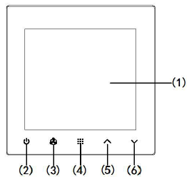
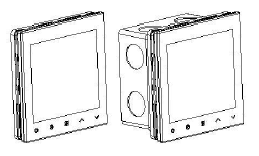
Thermostat Buttons and Switches
- Display area
- Power button(Short press to switch off thermostat;Long press into permanent hold mode in power on mode; Exit button)
- Fan speed option button (HI MED LOW AUTO)
- Menu button/time button/programmable button(Short press to set time;Long press to set programmable)
- Raise button
- Lower button
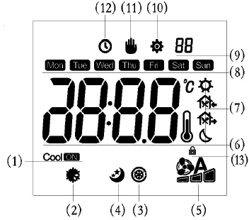
The Display
- Indicates thermostat is “calling” for cooling
- Indicates cooling mode
- Indicate filter dirty alarm
- Indicates room card activate
- Indicates fan status
- Indicates room temperature/ setting temperature/time
- Indicates programmable
- Indicates week
- Indicates No. in configuration
- Indicates setting mode
- Indicates permanent mode
- Indicates time setting
- Indicates key lock
- (11) and (12) show at same time meaning it’s in temporary hold mode
- (10) and (12) show at same time meaning it’s in the programming setting
INSTALL THE THERMOSTAT
- Gently opening the front panel by screwdriver at the bottom open mouth. Gently pulling the control panel straight off the base connector.
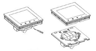 To screw for mounting thermostat in the wall.
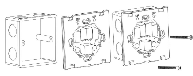
- Fix the cover on the base.
Wiring Diagram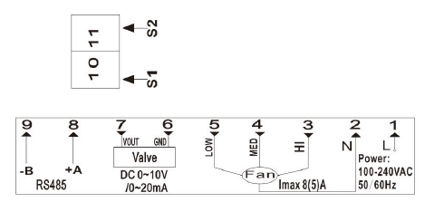
Thermostat Function Description
Cooling mode (Proportional-Integral(PI) control cooling)
Example: P-band is 2 °C
The valve cooling output PI and the temperature differential(room temperature and setting temperature) as following picture.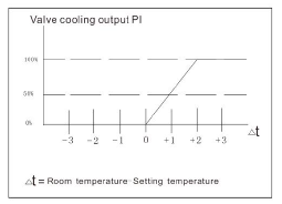
Fan speed instruction
Continuously press ![]() button, you can select HI speed, MED speed, LOW speed and AUTO speed, the LCD will display corresponding marks. If you select the AUTO speed: Room temperature is higher or equal 3 °C than the setting temperature, the fan will run HI speed; if the room temperature is higher or equal 2°C and lower or equal 3°C than the setting temperature, the fan will run MED speed. Other will run LOW speed. If you choose fan run with valve in parameter 6 of configuration,the Auto fan would stop if cooling valve close
button, you can select HI speed, MED speed, LOW speed and AUTO speed, the LCD will display corresponding marks. If you select the AUTO speed: Room temperature is higher or equal 3 °C than the setting temperature, the fan will run HI speed; if the room temperature is higher or equal 2°C and lower or equal 3°C than the setting temperature, the fan will run MED speed. Other will run LOW speed. If you choose fan run with valve in parameter 6 of configuration,the Auto fan would stop if cooling valve close
External sensor
When external sensor connected, thermostat will show temperature detected by external sensor. When external sensor removed or open circuit, thermostat will show temperature detected by ambient sensor.
Key lock
In power on status,long press  button to activate key lock or cancel the button lock. With different key lock option,refer parameter LF.
Room card
If room card is not present, it could set default setting temperature from configuration menu by parameter 9. If room card activate, it could set energy saving temperature from configuration menu by parameter 10.
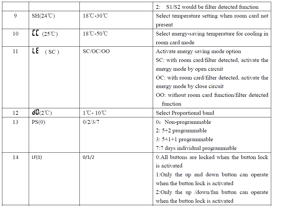
The configuration menu allows you to set certain thermostat operating characteristics to your system or personal requirements. Switch off the thermostat, long press buttons ![]() more than 3 seconds to enter the configuration menu, The display will show the first item in the configuration menu. Press
more than 3 seconds to enter the configuration menu, The display will show the first item in the configuration menu. Press![]() button to shift to the next menu item, use
button to shift to the next menu item, use  to select. To exit the menu, press the power button to switch off the thermostat. The thermostat will exit the configuration menu if no buttons are pressed within 20 seconds. The configuration menu chart summarizes the configuration options. In implicit parameter menu mode, long press button
 ![]() for 3 seconds, and all parameters will back to the initial value. An explanation of each option is as follows:
for 3 seconds, and all parameters will back to the initial value. An explanation of each option is as follows: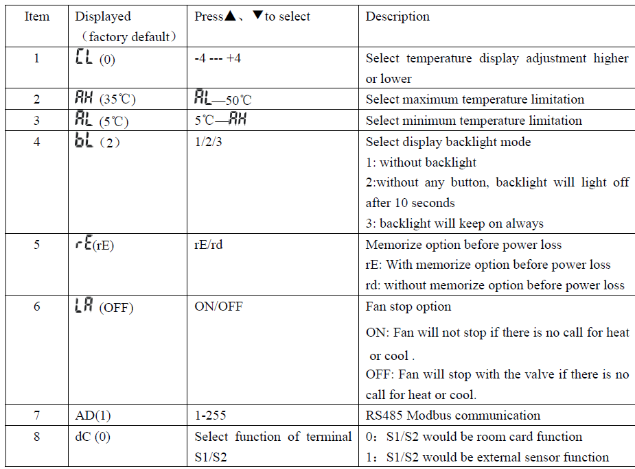
Programmable Setting
Long press ![]() over 3 second in power on it run into programmable setting menu (Keep you chose 5+2 programmable,5+1+1 programmable or 7 days programmable) .Press to set time/adjust the temperature. Press
over 3 second in power on it run into programmable setting menu (Keep you chose 5+2 programmable,5+1+1 programmable or 7 days programmable) .Press to set time/adjust the temperature. Press to go to next step Press
 ![]() to save what you setting and exit.
to save what you setting and exit.
Basic description
Command frame 1: Read the thermostat ON/OFF state
| Byte l | Byte 2 | Byte 3 | Byte 4 | Byte 5 | Byte 6 | Byte 7 | Byte 8 |
| Thermostat
address |
03(reado
ut |
00(start
address) |
00(start
address) |
00(regist
er count) |
0l(regist
er count) |
CRC low | CRC
high |
| comman | High | Low byte | High byte | Low byte | |||
| d code) | byte |
Response Franme Given By Thermostat
| Thermostat address | 03
(command code) |
02
(Bytes) |
00(ON/OFF
state high byte) |
xx(ON/OFF
state low byte) |
CRC low | CRC high |
Command frame 2: Read the thermostat mode state
| Byte l | Byte 2 | Byte 3 | Byte 4 | Byte 5 | Byte 6 | Byte 7 | Byte 8 |
| Thermostat | 03(readou | 00(start | 0l(start | 00(register | 0l(registe | CRC | CRC high |
| address | t | address) | address) | count) | r count) | low | |
| command | High byte | Low byte | High byte | Low byte | |||
| code) |
Response Franme Given By Thermostat
| Byte l | Byte 2 | Byte 3 | Byte 4 | Byte 5 | Byte 6 | Byte 7 |
| Thermostat address | 03
(command code) |
02
(Bytes) |
00(Mode status High byte) | xx(Mode status Low byte) | CRC low | CRC high |
Command frame 3: Read the thermostat fan speed state
| Byte l | Byte 2 | Byte 3 | Byte 4 | Byte 5 | Byte 6 | Byte 7 | Byte 8 |
| Thermostat | 03(readou | 00(start | 02(start | 00(register | 0l(registe | CRC | CRC high |
| address | t | address) | address) | count) | r count) | low | |
| command | High byte | Low byte | High byte | Low byte | |||
| code) |
Response Frame Given By Thermostat
| Byte l | Byte 2 | Byte 3 | Byte 4 | Byte 5 | Byte 6 | Byte 7 |
| Thermostat address | 03
(command code) |
02
(Bytes) |
00
Fan speed High byte |
xx
Fan speed Low byte |
CRC low | CRC high |
Command frame 4: Read the thermostat setting temperature
| Byte l | Byte 2 | Byte 3 | Byte 4 | Byte 5 | Byte 6 | Byte 7 | Byte 8 |
| Thermostat | 03(comman | 00(start | 03(start | 00(register | 0l(registe | CRC low | CRC high |
| address | d code) | address) | address) | count) | r count) | ||
| High | Low byte | High byte | Low byte | ||||
| byte |
Response Frame Given By Thermostat
| Byte l | Byte 2 | Byte 3 | Byte 4 | Byte 5 | Byte 6 | Byte 7 |
| Thermostat | 03 | 02 | xx (Setting | YY (Setting | CRC low | CRC high |
| address | (command | (Bytes | temperature) | temperature) | ||
| code) | ) | High byte | Low byte |
Command frame 5: Read the thermostat proportional valve position
| Byte l | Byte 2 | Byte 3 | Byte 4 | Byte 5 | Byte 6 | Byte
7 |
Byte 8 |
| Thermostat address | 03(command code) | 00(start address)
High byte |
04(start address)
Low byte |
00(registe r count)
High byte |
0l(registe r count)
Low byte |
CRC
low |
CRC
high |
Response Frame Given By Thermostat
| Byte l | Byte 2 | Byte 3 | Byte 4 | Byte 5 | Byte 6 | Byte 7 |
| Thermostat
address |
03
(command |
02
(Bytes) |
05(Proportional
valve position) |
xx(Proportion
al valve |
CRC low | CRC high |
| code) | High byte | position) | ||||
| Low byte |
Command frame 6: Read the thermostat current temperature value
| Byte l | Byte 2 | Byte 3 | Byte 4 | Byte 5 | Byte 6 | Byt
e 7 |
Byte 8 |
| Thermostat address | 03(command code) | 00(start
address) High byte |
05(start
address) Low byte |
00(registe
r count) High byte |
0l(registe
r count) Low byte |
CRC
low |
CRC
high |
Response Frame Given By Thermostat
| Byte l | Byte 2 | Byte 3 | Byte 4 | Byte 5 | Byte 6 | Byte 7 |
| Thermostat | 03 | 02 | xx(current | YY( current | CRC low | CRC high |
| address | (command | (Bytes) | temperature | temperature t | ||
| code) | value) | value ) | ||||
| High byte | Low byte |
Command frame 7: Read the thermostat external sensor’s temperature
| Byte l | Byte 2 | Byte 3 | Byte 4 | Byte 5 | Byte 6 | Byte
7 |
Byte 8 |
| Thermostat address | 03(command code) | 00(start address)
High byte |
06(start address)
Low byte |
00(register count)
High byte |
0l(register count)
Low byte |
CRC
low |
CRC
high |
Response Frame Given By Thermostat
| Byte l | Byte 2 | Byte 3 | Byte 4 | Byte 5 | Byte 6 | Byte 7 |
| Thermostat | 03 | 02 | xx(external | YY( external | CRC low | CRC high |
| address | (command | (Bytes) | sensor’s | sensor’s | ||
| code) | temperature ) | temperature) | ||||
| High byte | Low byte |
Command frame 8: Read the thermostat room card status (DC is 0)
| Byte l | Byte 2 | Byte 3 | Byte 4 | Byte 5 | Byte 6 | Byte
7 |
Byte 8 |
| Thermostat | 03(command | 00(start | 07(start | 00(register | 0l(register | CRC | CRC |
| address | code) | address)
High byte |
address)
Low byte |
count)
High byte |
count)
Low byte |
low | high |
Response Frame Given By Thermostat
| Byte l | Byte 2 | Byte 3 | Byte 4 | Byte 5 | Byte 6 | Byte 7 |
| Thermostat address | 03
(command code) |
02
(Bytes) |
00( room card status)
High byte |
x(room card status)
Low byte |
CRC low | CRC high |
Command frame 9: Read filter dirty status(DC is 2)
| Byte l | Byte 2 | Byte 3 | Byte 4 | Byte 5 | Byte 6 | Byte
7 |
Byte 8 |
| Thermostat address | 03(command code) | 00(start address)
High byte |
08(start address)
Low byte |
00(register count)
High byte |
0l(register count)
Low byte |
CRC
low |
CRC
high |
Response Frame Given By Thermostat
| Byte l | Byte 2 | Byte 3 | Byte 4 | Byte 5 | Byte 6 | Byte 7 |
| Thermostat address | 03
(command code) |
02
(Bytes) |
xx(filter dirty status)
High byte |
YY( filter dirty status)
Low byte |
CRC low | CRC high |
Command frame 10: Read the fan running status
| Byte l | Byte 2 | Byte 3 | Byte 4 | Byte 5 | Byte 6 | Byte
7 |
Byte 8 |
| Thermostat address | 03(command code) | 00(start
address) High byte |
09(start
address) Low byte |
00(register
count) High byte |
0l(register
count) Low byte |
CRC
low |
CRC
high |
Response Frame Given By Thermostat
| Byte l | Byte 2 | Byte 3 | Byte 4 | Byte 5 | Byte 6 | Byte 7 |
| Thermostat address | 03
(command code) |
02
(Bytes) |
xx(fan status ) High byte | YY( fan status) Low byte | CRC low | CRC high |
Command frame 11: Read the thermostat ON/OFF state
| Byte l | Byte 2 | Byte 3 | Byte 4 | Byte 5 | Byte 6 | Byte 7 | Byte 8 |
| Thermostat
address |
03(reado
ut |
00(start
address) |
0A(start
address) |
00(regist
er count) |
0l(regist
er count) |
CRC low | CRC
high |
| comman | High | Low byte | High byte | Low byte | |||
| d code) | byte |
Response Frame Given By Thermostat
| Thermostat
address |
03
(command |
02
(Bytes) |
00(ON/OFF
state high |
xx(ON/OFF
state low |
CRC low | CRC high |
| code) | byte) | byte) |
Command frame 12: Read the thermostat fan speed state
| Byte l | Byte 2 | Byte 3 | Byte 4 | Byte 5 | Byte 6 | Byte 7 | Byte 8 |
| Thermostat | 03(readou | 00(start | 0B(start | 00(register | 0l(registe | CRC | CRC high |
| address | t | address) | address) | count) | r count) | low | |
| command | High byte | Low byte | High byte | Low byte | |||
| code) |
Response Frame Given By Thermostat
| Byte l | Byte 2 | Byte 3 | Byte 4 | Byte 5 | Byte 6 | Byte 7 |
| Thermostat address | 03
(command code) |
02
(Bytes) |
00
Fan speed High byte |
xx
Fan speed Low byte |
CRC low | CRC high |
Command frame 13: Read thermostat setting temperature
| Byte l | Byte 2 | Byte 3 | Byte 4 | Byte 5 | Byte 6 | Byte 7 | Byte 8 |
| Thermostat | 03(comman | 00(start | 0C(start | 00(register | 0l(registe | CRC low | CRC high |
| address | d code) | address) | address) | count) | r count) | ||
| High | Low byte | High byte | Low byte | ||||
| byte |
Response Frame Given By Thermostat
| Byte l | Byte 2 | Byte 3 | Byte 4 | Byte 5 | Byte 6 | Byte 7 |
| Thermostat | 03 | 02 | xx (Setting | YY (Setting | CRC low | CRC high |
| address | (command | (Bytes | temperature) | temperature) | ||
| code) | ) | High byte | Low byte |
Set the thermostat frame format
Command frame 1 (give by upper computer) set the thermostat ON/OFF
| Byte l | Byte 2 | Byte 3 | Byte 4 | Byte 5 | Byte 6 | Byte 7 | Byte 8 |
| Thermostat address | 06(com mand
code) |
00(start address)
High byte |
00(start address
Low byte) |
00(Setting value high
byte) |
xx(Setting value low
byte) |
CRC low | CRC high |
Command frame 2 (give by upper computer) set the mode
| Byte l | Byte 2 | Byte 3 | Byte 4 | Byte 5 | Byte 6 | Byte 7 | Byte 8 |
| Thermostat address | 06(com mand
code) |
00(start address)
High byte |
0l(start address
Low byte) |
00(Setting value high
byte) |
xx(Setting value low
byte) |
CRC
low |
CRC high |
Command frame 3 ( give by upper computer) set the fan speed
| Byte l | Byte 2 | Byte 3 | Byte 4 | Byte 5 | Byte 6 | Byte 7 | Byte 8 |
| Thermostat address | 06(com
mand code) |
00(start
address) High byte |
02(start
address Low byte) |
00(Setting
value high byte) |
xx(Setting
value low byte) |
CRC
low |
CRC
high |
Command frame 4 ( give by upper computer) set the setting temperature
| Byte l | Byte 2 | Byte 3 | Byte 4 | Byte 5 | Byte 6 | Byte 7 | Byte 8 |
| Thermostat | 06(com | 00(start | 03(start | xx(Setting | YY(Setting | CRC low | CRC |
| address | mand | address) | address | temperature | temperature | high | |
| code) | High | Low byte) | high byte) | low byte) | |||
| byte |
REFERENCE:
DOWNLOAD MANUALS:
Hexa Controls RT226-J29 Modulating Digital Thermostat Installation and Operation instructions
![]()
Hexa Controls RT226-J29 Modulating Digital Thermostat Installation and Operation instructions
Leave a Reply