
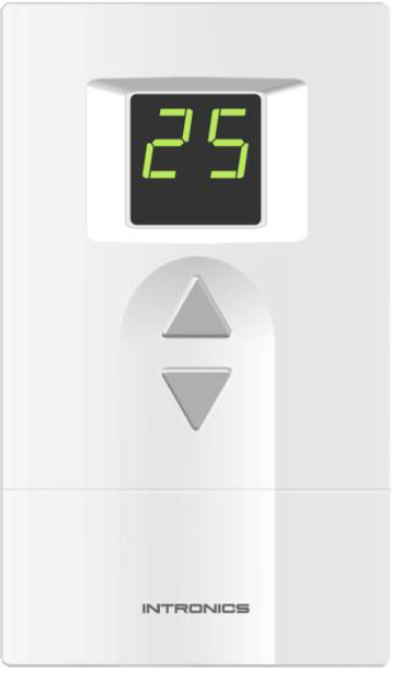
INTRONICS PI04 Digital Thermostat
APPLICATION
PI series is a 24 VAC/VDC Modulating Digital Thermostat that provides Proportional + Integral (P+I) control for optimum temperature control and comfort in HVAC system. It is used with the single fan speed. Other available features include selection of Minimum / Maximum setting temperature, Digital input for energy savings, Mode of display. The remote temperature sensor can also be provided as the optional.
| Model | Mounting | Operating voltage | Type of control | Power on/off switch |
| PI – 03 | Vertical | 24 VAC | Modulating 0-10V or 2-10V | No |
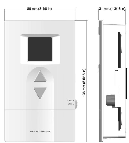
| PI – 04 | Vertical | 24 VAC | Modulating 0-10V or 2-10V | Yes |
FEATURES
- Stylish design with digital display.
- Minimum temperature setting from 5 – 23 ºC (Default 11 ºC).
- Maximum temperature setting from 16 – 34 ºC (Default 30 ºC).
- Compatible with 10 different characteristics of modulating valve/damper.
- Setting of calculating position cycle.
- Kp setting.
- Ti setting.
- Temperature offset –2 to +2 ºC (Default 0 ºC).
- Digital input for energy savings.
- Mode of display : Room temperature, Setting temperature or % of valve/damper opening.
- Remote sensor (optional) with auto detect of temperature sensor (internal or remote sensor).
- Sensor error alarm.
- EEPROM permanently retains user setting in case of power loss.
SPECIFICATIONS
| Power supply | 24 Vac nominal, 18 – 30 Vac, 50/60 Hz. or 24 Vdc nominal, 18-30 Vdc |
| Electrical rating | 0.8 Amp maximum |
| Temperature setting range | 5 – 34 ºC |
| Operating relative humidity | 5 to 90 % RH, non condensing |
| Output | Modulating 0-10V or 2-10 V Direct/Reversing Actuating |
| Mounting | Directly onto wall or 2”x 4 “ vertical junction box |
DIMENSIONS
OPERATION
- Power on off (for Model PI – 04 only)
Use ON/OFF switch to turn on / off the system. - Temperature setting
Use △ or ▽ change the temperature setting. - Minimum temperature set point
The system provides the facility to program the minimum setting point in a range of 5 – 23 ºC (with 2 ºC incremental). - Maximum temperature set point
The system provides the facility to program the maximum setting point in a range of 16 – 34 ºC (with 2 ºC incremental). - PI Control parameter
The system provides the facility to program the value of Kp and Ti. - Temperature offset
The temperature offset can be set in a range of – 2 to + 2 ºC. - Display mode
The Display can be programmed to display room temperature, setting temperature or % of valve/damper opening. - Temperature display in decimal number
In case of selecting program 8.0 and 9.1, Press △and ▽key simultaneously to toggle showing room temperature in integer or decimal number. To exit this program, cut off the power. - Remote sensor (optional)
The Remote sensor can be provided as the option. It can be the temperature module, epoxy or pipe type. The system will automatically detect whether the internal or the Remote sensor is used.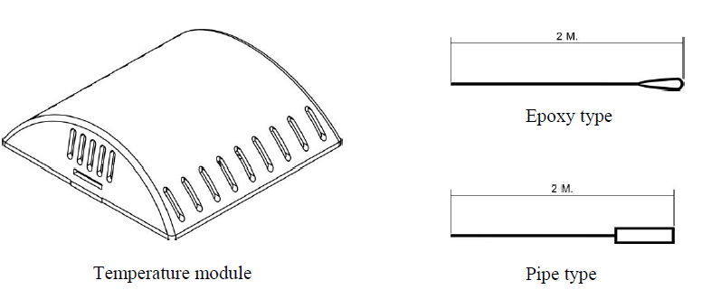
- Digital input for energy savings
There is a Digital input port for energy savings provided in the system. If the input is NO contact, the system will not do anything. If the input is NC contact, it will delay for 2 minutes and then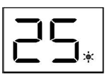
- Sensor error alarm
If the temperature sensor (either internal or remote) is failed, Display will show Er in blinking. - Target error alarm
If the target of the valve/damper opening can not be reached within 2 minutes (for Feed back type only), Display will show Ef in blinking.
INSTALLATION
Read these instructions thoroughly before installing product. Failure to follow these instructions could damage the product or cause a hazardous condition. Check the voltage and current ratings on the product to ensure that it is suitable for your application. Installer must be a trained, experienced service technician. Check product for proper operation after installation
Mounting Location
- Mount the thermostat approximately 5 ft. (1.5 m) above the floor in a location that is free from direct sunlight, heat from appliances, hot or cold air from ducts, concealed pipes and chimneys, and drafts or dead spots behind doors or in
- corners. Do not mount on an exterior wall, if possible. Failure to locate the thermostat mounting as indicated will result in poor temperature control.
NOTE: Level thermostat mounting is for appearance only and is not required for proper thermostat operation.
Mounting Thermostat
Take out the back plate by removing the locking screw (if any) at the bottom of the thermostat. Use a flathead screwdriver to unlock the snaps. Lift and pull it up to remove back plate.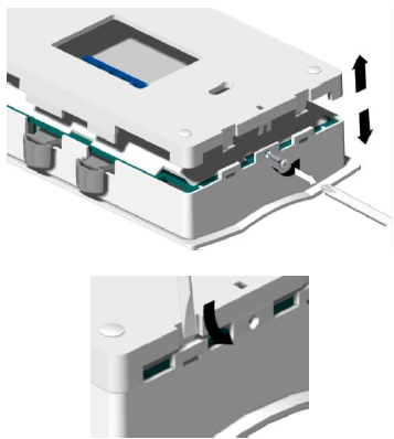
The 18-22 gauge wire is recommended for wiring.
Using back plate as a guide, mark two mounting holes on the wall. Drill two mounting holes. Place anchors (provided) into the holes until flush with the hole. Position back plate on the wall and thread the wires from the heating and cooling equipment through the wiring hole. Holding the back plate in place on the wall, secure it to the wall using mounting screws (provided).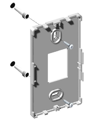
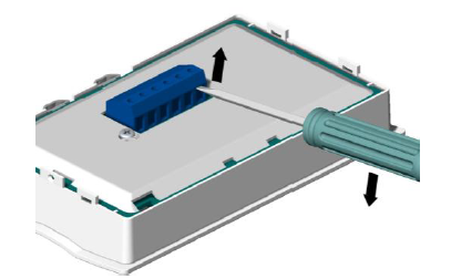
Wiring
- Pull the connector from the back of thermostat by inserting screwdriver at the base of the connector and gently lift up.
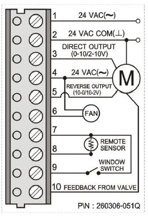
Note: Only one terminal from terminal 3&5 is connected. It is subjected to the application. - Loosen the terminal screw, strip the wire and connect the wire as shown in fig. 8 Firmly tighten terminal screw when finished.
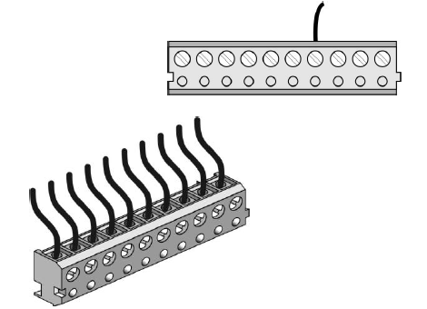
- Place the terminal back to the thermostat, make sure it has the same orientation like in the picture described at the back. Snap the thermostat to its back plate.
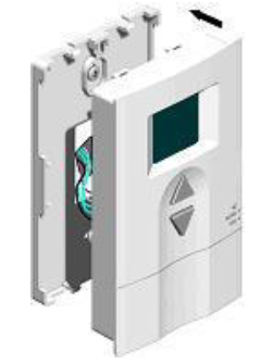
Fig.9 Installing a thermostat
Secure the thermostat by tightening the screw provided to protect the thermostat from unwanted access.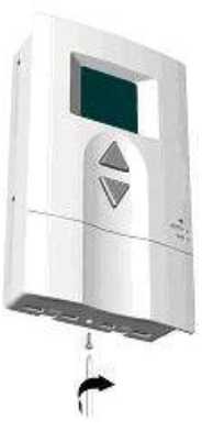
INSTALLER SETUP
The following instructions provide information to test the cooling equipment and to change operating parameters from the factory settings.
Enter Installer Setup
- Press and hold △and ▽ key simultaneously for 10 seconds to enter installer setup. The dot between the two digit display lits showing the Installer Setup mode
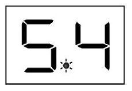
- The first digit shows the Programming number.
- The second digit shows the Parameter setting. Now follow the following steps to change each of the settings. Each time you press △key, you will advance to the next Programming number. The ▽key is used for Parameter setting.
Program 1 : Minimum temperature setting
To set the minimum temperature (5-23 ºC) allowed for the user.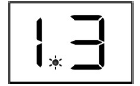
- Press △ key until the first digit is 1.
- Press ▽ key until the second digit is as required. See table below
| Second digit displays | 0 | 1 | 2 | 3 | 4 | 5 | 6 | 7 | 8 | 9 |
| Min. temp. setting | 5 | 7 | 9 | 11 | 13 | 15 | 17 | 19 | 21 | 23 |
Program 2 : Maximum temperature setting
To set the maximum temperature (16-34 ºC) allowed for the user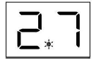
- Press △key until the first digit is 2.
- Press ▽key until the second digit is as required. See table below
| Second digit displays | 0 | 1 | 2 | 3 | 4 | 5 | 6 | 7 | 8 | 9 |
| Max. temp. setting | 16 | 18 | 20 | 22 | 24 | 26 | 28 | 30 | 32 | 34 |
Program 3: Type of valve/damper
There are several types of valve/damper subject to the types actuating, feed back and direction. Program the thermostat to match with the type of valve/damper used.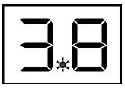
- Press △key until the first digit is 3.
- Press ▽key until the second digit is as required. See table below.
| Second digit displays | 0 | 1 | 2 | 3 | 4 | 5 | 6 | 7 | 8 | 9 |
| Type of actuating | 0-10V | 2-10V | 0-10V | 2-10V | 0-10V | 2-10V | 0-10V | 2-10V | 0-10V | 2-10V |
| Type of feed back | 0-10V | 0-10V | 2-10V | 2-10V | 0-10V | 0-10V | 2-10V | 2-10V | None | None |
| Feed back direction | DA | DA | DA | DA | RA | RA | RA | RA | None | None |
Program 4: Setting of Calculating position cycle
This program is used to select interval time of position calculation for valve control. It can be set in a range of 30-120 seconds. The control will delay the next operation of the valve/damper until the current operation is completed.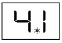
- Press △key until the first digit is 4.
- Press ▽ key until the second digit is as required. See table below.
| Second digit displays | 0 | 1 | 2 | 3 | 4 | 5 | 6 | 7 | 8 | 9 |
| Opening time (sec.) | 30 | 40 | 50 | 60 | 70 | 80 | 90 | 100 | 110 | 120 |
Program 5: Kp setting
Kp is the proportional factor that control the opening of the valve/damper. The higher Kp, the faster the room temp. is brought to the set temp. However the fluctuation of the room temp. is also higher. Then Kp shall be set properly.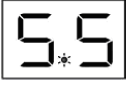
- Press △key until the first digit is 5.
- Press ▽ key until the second digit is as required. See table below.
| Second digit displays | 0 | 1 | 2 | 3 | 4 | 5 | 6 | 7 | 8 | 9 |
| Kp | 1 | 2 | 4 | 6 | 8 | 10 | 12 | 14 | 16 | 18 |
Note : Default setting is 5 (Kp = 10).
Program 6 : Ti setting
Ti is the integral factor that control the opening of the valve/damper. The higher Ti, the slower the room temp. is brought to the set temp. However the fluctuation of the room temp. is less. Then Ti shall be set properly.
- Press △key until the first digit is 6.
- Press ▽ key until the second digit is as required. See table below.
| Second digit displays | 0 | 1 | 2 | 3 | 4 | 5 | 6 | 7 | 8 | 9 |
| Ti | 40 | 50 | 60 | 70 | 80 | 90 | 100 | 120 | 160 | 200 |
Program 7 : Temperature offset
- The temperature offset of the sensor’s reading can be set in a range of –2 to 2 ºC with a resolution of 0.5ºC.

- Press △key until the first digit is 7.
- Press ▽ key until the second digit is as required. See table below
| Second digit displays | 0 | 1 | 2 | 3 | 4 | 5 | 6 | 7 | 8 |
| Offset temp. (ºC) | -2 | -1.5 | -1 | -0.5 | 0 | 0.5 | 1 | 1.5 | 2 |
Program 8 : Display mode
The user can set the Display to show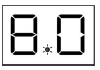
- Room temperature or
- Set temperature or
- Valve/damper opening in % (by controller’s command)
- Valve/damper opening in % (by actual). This can not be applied if No feed back type is used. Display will show 00.
- Press △key until the first digit is 8.
- Press ▽key until the second digit is as required. See table below
| Second digit displays | 0 | 1 | 2 | 3 |
| Display | Room temp. | Set temp. | % valve/damper (controller’s command) | % valve/damper (actual) |
Program 9: Temperature display in decimal number
The user can set the temperature display to show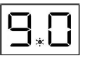
- Integer number
- Decimal number
- Press △key until the first digit is 9.
- Press ▽ key until the second digit is as required. See table below
| Second digit displays | 0 | 1 |
| Display | Integer number | Decimal number |
Reference:
Download manual:
INTRONICS PI04 Digital Thermostat INSTALLATION MANUAL
![]()
Leave a Reply