
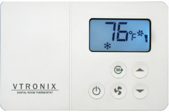
Vtronix T5575B Digital Fancoil Thermostat
INTRODUCTION
The following sections describe the features and functional specifications of the LCD Digital room thermostat.
INSTALLATION
Read these instructions thoroughly before installing the product. Failure to follow these instructions could damage the product or cause A hazardous condition. Check the voltage and current ratings on the product to ensure that it is suitable for your application. Installer must be a trained, experienced service technician. Check product for proper operation after installation.
CAUTION
Damage to cooling system may occur. Disconnect power from the equipment at the main breaker/fuse block while installing the thermostat.
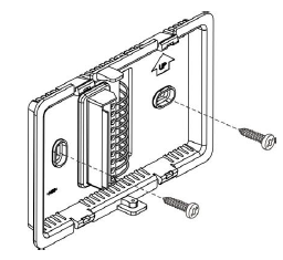
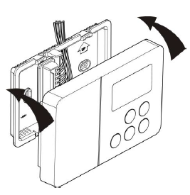
Lift and open top side using a screwdriver.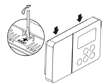
Installation A (wires through the wall)
- Use cable size 0.5-1 sq. mm to connect the wires into terminals.
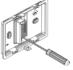
- Installing back plate into the wall with screws.
Installation B (wires on wall)
- Cut the plastic and open the hole with pliers
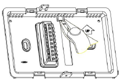
- Use cable size 0.5-1 sq. mm connect the wires into terminals.
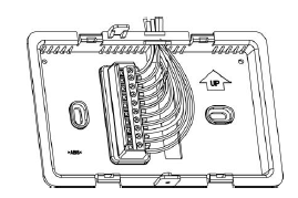
- Installing back plate into the wall with screws.
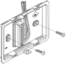
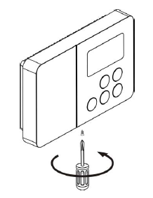
- Install the front case, carefully inspect wiring as per diagram before mounting thermostat
- Tighten the screw firmly.
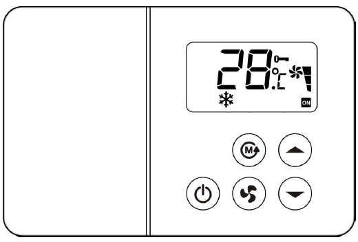
FEATURES
POWER
Press![]() the button to turn on/off the equipment. When turned on, it will operate according to the last program setting.
the button to turn on/off the equipment. When turned on, it will operate according to the last program setting.
FAN
Press![]() button to select the fan speed (auto, high, medium or low mode).
button to select the fan speed (auto, high, medium or low mode).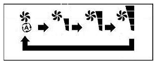
When the fan speed is put in auto mode, the speed will be adjusted automatically according to the difference between the room temperature and the setpoint temperature.
- If the difference is 3 ºC (6oF ) or more, the speed is high.
- If the difference is 2 ºC (4oF ), the speed is medium.
- If the difference is 1 ºC (2oF ) or less, the speed is low.
Note: The FAN button can be used only in the FAN, COOL, HEAT and AUTO modes, it can not be used in the DRY mode
TEMPERATURE SETTING
The setpoint temperature can be set in the range of 15-30 ºC or 58-88 ºF by pressing the ![]() buttons. The LCD display on the unit will show the setpoint temperature and Set icon flashing for 5 seconds. The system can be preset from the factory to display the temperature in ºC or ºF.
buttons. The LCD display on the unit will show the setpoint temperature and Set icon flashing for 5 seconds. The system can be preset from the factory to display the temperature in ºC or ºF.
MODE
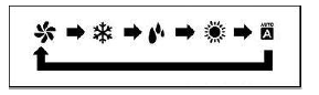
- By pressing the MODE button, the air conditioner can be put in 3 operating modes (fan, cool, dry)
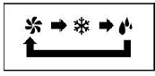
- 5 operating modes (fan, cool, dry, heat, auto)
Fan: When the system is put in the Fan mode, the system will operate as fan only. The ![]() buttons can not be used
buttons can not be used
Cool: When the system is put in the Cool mode, the system will operate as an air conditioner. The cool valve or compressor will
-
- operate if Troom > Tset +1
- stop if Troom > set
Dry: When the system is put in Dry mode, the system (cool valve or compressor) will operate as a dehumidifier with the algorithm below.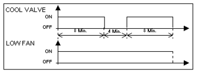
Heat: The system can be preset from the factory to control Heat Valve or Heat Pump or Electric Heater.
Heat Valve (Hot water valve)
When the system is put in Heat mode (Hot water), the system will operate as a hot water fan coil unit. The heat valve will
- operate if Troom < Tset -1
- stop if Troom < Tset
Heat Pump
When the system is put into heat mode (heat pump), the system will operate as a heat pump unit. The reversing valve will be activated in heat mode. The control logic for heat pump mode will be
- operate if Troom < Tset -1
- stop if Troom > Tset
Heater (Electric-heater)
When the system is put in Heat mode (Electric-heater), the system will operate as a heater. The electric-heater will
- operate if Troom< Tset -1
- stop if Troom< Tset
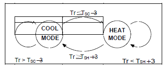
Auto: When the system is put in Auto mode, the system will switch between Heat and Cool automatically The auto mode will operate as follows
Define
- Tr = room temperature
- Ts = setting temperature
- TSC = temperature used as the decision point while in COOL mode
- = TS +1
- TSH = temperature used as the decision point while in HEAT mode
- = TS -1
- The system will switch from COOL to HEAT mode if
- Tr < TSC -3
- The system will switch from HEAT to COOL mode if
- Tr > TSH +3
- Tr > TSH +3
The default remote setback option is for setback via a MODE button press on thermostat. In this mode, the thermostat can quickly be setback by pressing and holding down the MODE button for more than 3 seconds. When the system is put in this mode, the LCD will show the Setback icon.(see IS CODE P7)
Setback mode
For Cool mode, the system operates at 25 ºC (77 ºF) and Auto fan speed. For Heat mode, the system operates at 20 ºC (68 ºF) and Auto fan speed. For Auto mode, the system operates as above for Cool and Heat modes. To exit from this mode press and hold the MODE button for more than 3 seconds.
Note :
- It will automatically exit from the Setback mode if the operating mode is changed.
- Turning the unit on/off will not exit from the Setback mode
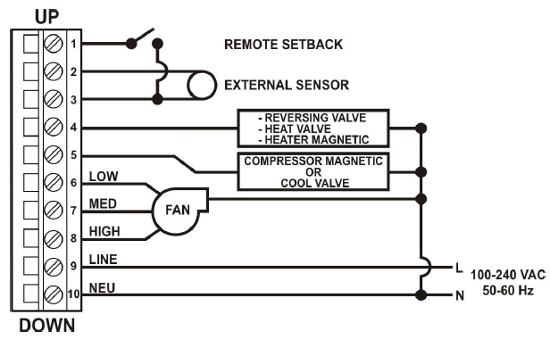
REMOTE SETBACK
Remote setback is activated by a dry contact closure on the remote setback input from occupancy sensor, time switch, or hotel card key. The thermostat controls to setback setpoints for increased energy savings (Setback mode). When the system is put in this mode, the LCD display will show the Setback icon.When setback is active, all buttons on the thermostat are disabled. However, the button combinations to access the Installer setup (IS) remain enabled (see IS CODE P7)
INSTALLER SETUP (IS) MODE
- To enter Install Setup Mode
- Press and hold both
 and
and  button for 3 seconds.
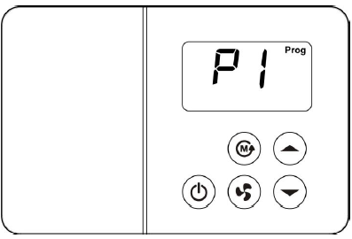
To enter the setup parameters:
- Press
 buttons to select IS code (P1 – P8)
 - Press MODE button to set the option value.
- Press buttons to change the option value.
- After the desired value displays, press MODE button to store your value selection and display the next IS code.
Table. Installer Setup (IS) Codes and Options.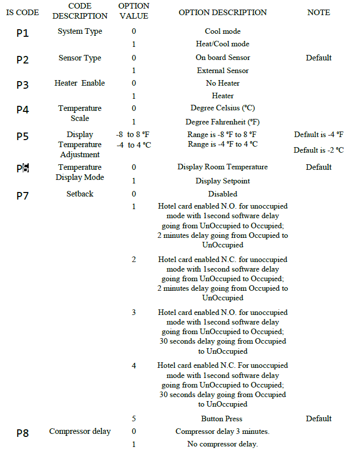
LOCK SYSTEM
- Press and hold MODE
 , and
, and buttons for 5 seconds.All buttons are locked out,The LCD displays
- To unlock the thermostat, press and hold MODE, and buttons for 5 seconds.
SYSTEM FEATURES
REVERSING VALVE CHANGE PROTECTION (FOR HEAT PUMP)
Whenever the reversing valve is to change its state, either OFF ON or ON OFF, it can be done only after the compressor stops at least one minute.
COMPRESSOR DELAY PROTECTION
If the unit is preset to heat/cool with compressor delay protection, each time the compressor is off, there will always be a minimum 3-minute delay before the compres sor can restart. In case of power interruption,
the system will have a random compressor delay in the range of 3-4 minutes.
AUTO RESTART
All the setpoint parameters are kept in nonvolatile memory. When there is a power failure and return to normal, the system will resume its operation with the same setpoint parameters.
WATCHDOG
There is a watchdog circuit to watch the operation of the microprocessor. If it malfunctions, this circuit will reset the microprocessor automatically.
SENSOR ERROR ALARM
If the room sensor has an open/short circuit, the controller will stop the equipment and the display will show rE flashing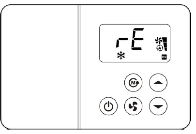
Compressor/ Valve/ Heater status display
If the compressor or valve or heater is ON, the LCD will show an ON icon.
ELECTRICAL CHARACTERISTICS
| POWER SUPPLY: | 100-240 VAC, 50/60 Hz |
| TEMPERATURE:
Temperature accuracy Storage temperature Ambient temperature Setting temperature range |
+1ºC |
| 0 – 70 ºC | |
| 10 – 50 ºC | |
| 15 – 30 ºC (58 – 88 ºF) | |
| RELAY:
Rating (inductive load) – Maximum switching capacity |
2 A @ 240 V (AC) 4 A @ 120 V (AC) |
| REMOTE SETBACK INPUT:– Minimum current | 10 mA @ 5 V (DC) |
| EXTERNAL SENSOR:NTC type 6.8 kohm @ 25 ºC |
WIRING DIAGRAM
REFERENCE:
DOWNLOAD MANUAL:
Vtronix T5575B Digital Fancoil Thermostat FUNCTIONAL SPECIFICATION
Vtronix T5575B Digital Fancoil Thermostat FUNCTIONAL SPECIFICATION
Leave a Reply