
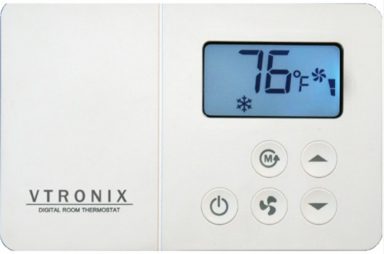
Vtronix TF85L-200 Digital Room Thermostat
APPLICATION
The TF85L Thermostat provides 24VAC single-stage temperature control of 2 pipe and 4 pipe fan-coil applications with automatic control of a 3 speed fan along with manual heat/cool changeover. The TF85L Thermostat is mercury free and requires no batteries. All set points are retained permanently in non-volatile memory in case of a power interruption.
WARNING
- Improper installation, adjustment, alteration, service, maintenance or use can cause an explosion, fire, electrical shock or other conditions which may cause personal injury, death or property damage.
- Observe all warning and caution notices in this document and those posted on the equipment.
- Wear safety glasses, gloves and protective clothing.
- Do not operate equipment or apply electrical power without panels in place.
- Normal system operation will cause some components and surfaces to become hot and can cause burns.
- Before installing, modifying or servicing the system, main electrical disconnect switch must be in the OFF position. There may be more than one disconnect switch. Lock out and tag switches with a suitable warning label. Electrical shock can cause personal injury or death.
- All electrical power should be turned off when servicing or repairing electrical components. Extreme caution should be observed when trouble shooting electrical components when power is applied. Observe all warning notices posted on equipment.
SPECIFICATIONS
- POWER SUPPLY:24 VAC system 18 – 30 VAC, 50/60 Hz
- TEMPERATURE :
- Temperature accuracy ± 1.8 °F
- Storage temperature 32 – 158 °F
- Ambient temperature 50 – 122 °F
- Setting temperature range 64 – 85 °F
- Deadband (Auto changeover model) ± 1 °F of Setpoint
- FAN RELAY, HEAT and COOL RELAY : (P4-P8)
Rating (resistive load)- Maximum switching capacity 2 A 277 VAC 3 A 125 VAC
- Delay time (HEAT and COOL RELAY) 1 minute or 3 minute (default)
- EXTERNAL SENSOR (OPTIONAL) NTC TYPE 6.8 Kohm @ 77 °F
INSTALLATION
Read these instructions thoroughly before installing product. Failure to follow these instructions could damage the product or cause a hazardous condition. Check the voltage and current ratings on the product to ensure that it is suitable for your application. Installer must be a trained, experienced service technician. Check product for proper operation after installation.
CAUTION
Damage to heating and cooling system may occur. Disconnect power from the equipment at the main breaker/fuse block while installing the thermostat.
Mounting Location
Mount the thermostat approximately 5 ft. (1.5m) above the floor in a location that is free from direct sunlight, heat from appliances, hot or cold air from ducts, concealed pipes and chimneys, and drafts or dead spots behind doors or in corners. Do not mount on exterior wall, if possible. Failure to locate thermostat mounting as indicated will result in poor temperature control.
Note: Level thermostat mounting is for appearance only and is not required for proper thermostat operation.
Mount and Wire the Thermostat
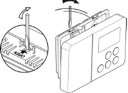
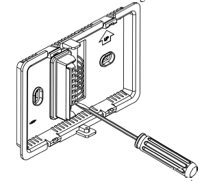
- Separate front of the thermostat from the rear case by using screwdriver to twist and open the locking tab as shown. Do not push on the LCD as it will damage it. Do not twist or bend the thermostat.
- Using the mounting bracket base as a guide, mark two mounting holes on the wall. Drill two mounting holes. Place anchors (provided) into the holes until flush with the hole. Position bracket on the wall and insert the wires from the heating and cooling equipment through the wiring hole. Holding the bracket and rear case in place on the wall, secure it to the wall using mounting screws (provided).
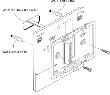
- For mounting thermostat directly on the wall (optional), drill two mounting holes (4-5/16 inch apart). Place anchors into the holes until flush with the hole. Holding the rear case in place on the wall, secure it to the wall using mounting screws (provided) as Fig.3
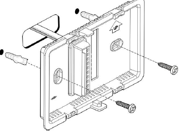
- Color-coded 18-22 gauge wire is recommended for wiring. All wiring must follow local electrical code. Loosen the terminal screw on the thermostat, strip the wire and connect the wire as shown in Fig. 4. Firmly tighten terminal screw when finished. Follow wiring diagram
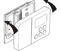
- Install the front case, carefully inspect wiring as per diagram before mounting thermostat
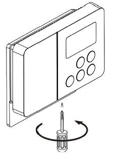
- Tighten the screw
WIRING DIAGRAM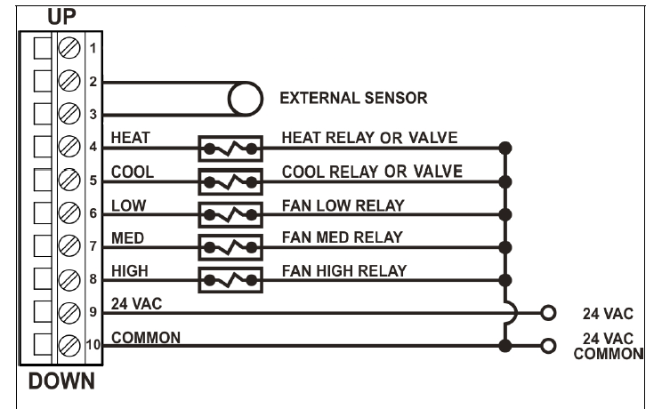
SET UP
Set up mode
Press and hold![]() , and
, and![]() buttons at the same time for 3 seconds, the display will show the existing set up as per Table 1. Note that all 3 buttons have to be pressed simultaneously.
buttons at the same time for 3 seconds, the display will show the existing set up as per Table 1. Note that all 3 buttons have to be pressed simultaneously.
Note
- For T200 manual changeover, applies in cool mode only
- For T200 manual changeover, applies in heat mode only
Example 1 : The Display shows P2 steady means the thermostat is set up for Continuous Fan operation
Change the Set Up Parameters
- While in set up mode, press
 button to go to the required set up parameter.
 - To change the set up as listed in Table 1, press
 button.
 - Repeat (a) & (b) for the next set up parameter.
- Press
 button to exit from the set up mode.
Note: If![]() button is pressed before exiting from the set up mode (Section d above), the thermostat will exit without changing the setup parameters. P4 setting applies only when P2 is set to Cycled Fan
button is pressed before exiting from the set up mode (Section d above), the thermostat will exit without changing the setup parameters. P4 setting applies only when P2 is set to Cycled Fan
OPERATION
Power
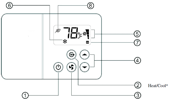
Press button to turn on/off the equipment. The thermostat will operate to the set point stored in non volatile memory.
Heat/Cool (For Manual changeover only)
- Press the button to change the current mode.
- Cool Mode – LCD display
 shows
shows icon.
icon. - Heat Mode – LCD display shows
 icon.
icon.
Note: – This button is deactivated for Auto changeover model. Heat/Cool mode can not be changed.
Fan
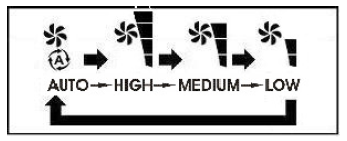
- Press
 button to select the fan speed in the following sequence.
 - LCD
 will show the status of the fan
Auto mode icon
The speed will be adjusted according to the difference between the room and the setpoint temperature.
- If the difference is 4°F or more, the fan will run at high speed.
- If the difference is 3°F, the fan will run at medium speed.
- If the difference is 2°F, or lower, the fan will run at low speed.
Note : Fan speed defaults to Automatic after 1 hour if it is changed by the user to a particular speed.
Continuous Fan
FAN is always on in High, Medium or Low speeds as long as the thermostat is powered.
Cycled Fan Standard
Fan is on when the heat or cool outputs are on (on cycle). Automatic fan operation is active in the on cycle. When the heat or cool outputs are off (off cycle), the Fan output is off. The Fan icons (Auto, High, Med and Low) are all turned off. The![]() button is deactivated in the off cycle. During the on cycle the fan speed can be manually changed. The fan will turn off in the off cycle and revert back to the selected fan speed during the on cycle.
button is deactivated in the off cycle. During the on cycle the fan speed can be manually changed. The fan will turn off in the off cycle and revert back to the selected fan speed during the on cycle.
Cycled Fan Override
Fan is on when the heat or cool outputs are on (on cycle). Automatic fan operation is active in the on cycle. When the heat or cool outputs are off (off cycle), the Fan output is off. The Fan icons (Auto, High, Med and Low) are all turned off. The button can be activated in the off cycle. The appropriate Fan icon (High, Med and Low) is turned on and the appropriate output is energized. It stays on this speed during the on cycle as well as the off cycle. This is subject to the automatic fan speed default timer.
Warning: This mode should not be selected for hydronic applications with no control valves.
Excessive heating can result if the Fan is turned on manually
Auto Fan Speed Timer
Fan speed defaults back to Automatic after 1 hour (or 3 hours based on P1 flashing setting) if it is changed to a particular speed.
Temperature setting
- Press button for setting the temperature in a range of 64 – 85 °F . But High and Low setting will depend on P5 and P6
- Display will show the new temperature setting for 5 seconds.
T200 Manual changeover
- In Cool mode, setting range will be 64-85°F or 70-85°F (set in P5).
- In Heat mode, setting range will be 64-85°F or 64-78°F (set in P6).
T201 Auto changeover
- Low setting temperature will be 64°F or 70°F (set in P5).
- High setting temperature will be 85°F or 78°F (set in P6).
Note: – icon on LCD display 6 indicates the auto changeover model.
System status
Display at 7 shows ON when there is a demand for heating or cooling. The LCD ON icon will flash when the delay time is activated. Default system delay time is 3 minutes.
Sensor Error Alarm
If the thermostat temperature sensor is defective, the thermostat will turn off the equipment and start flashing “SE” on the display.
Auto Restart
All the setup parameters are stored in non volatile memory. When there is a power failure and return to normal, the thermostat will resume operation with the previous setup parameters.
External Sensor
![]() icon on LCD display 8 indicates that the external sensor has been connected to terminals 2 and 3. In this case, the thermostat is controlling to the temperature sensed on the external sensor.
icon on LCD display 8 indicates that the external sensor has been connected to terminals 2 and 3. In this case, the thermostat is controlling to the temperature sensed on the external sensor.
VTRONIX, LLC Po Box 267096, Weston, FL 33326
Copyright © 2017 Vtronix Document no. 170064-110E (Rev.00)
REFERENCE:
DOWNLOAD MANUAL:
Vtronix TF85L-200 Digital Room Thermostat INSTALLATION MANUAL
![]()
Vtronix TF85L-200 Digital Room Thermostat INSTALLATION MANUAL
Leave a Reply